Self Heating Battery System

a self-heating, battery technology, applied in the direction of electrochemical generators, electrical devices, electric vehicles, etc., can solve the problems of large amount of heat generated, inability to quickly change the voltage output of the inductor, and inability to do, so as to increase the energy delivering ability of the battery, increase the switching rate, and increase the effect of energy supply to external loads

Active Publication Date: 2012-05-24
STRYTEN ENERGY LLC
View PDF0 Cites 68 Cited by
  • Summary
  • Abstract
  • Description
  • Claims
  • Application Information

AI Technical Summary

Benefits of technology

[0015]In another embodiment of the invention the energy storage device is an inductor that magnetically stores energy. The battery terminals are connected to the inductor terminals by a switching circuit. The magnetic energy will build up inside the inductor at the same time as the current increases in the inductor and the terminal voltage of the battery drops. The inductor is disconnected when either the battery terminal voltage falls below a preset threshold or when the current through the inductor exceeds a preset threshold. This protects the battery from damage due to over discharge. The switching and inductor system is protected from excessive current because as the battery becomes warmer it can supply more energy to external loads. Once the battery terminals are disconnected from the inductor, the magnetic field collapse which causes the voltage at the output of the inductor to rapidly change. At this time the inductor is then switched to the terminals of the battery so that the magnetically stored energy is delivered back i

Problems solved by technology

Therefore, large amounts of heat can be generated by reliance upon battery impedance.
Once the battery terminals are disconnected from the inductor, the magnetic field collapse which causes the voltage at the output of the

Method used


Image

  • Self Heating Battery System
  • Self Heating Battery System

Examples


Embodiment Construction

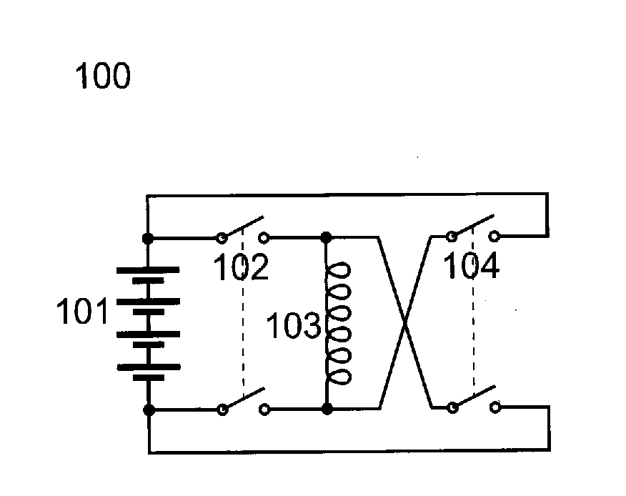
[0023]Referring to FIG. 1, there is shown one embodiment of the battery self heating system (100) comprising a battery (101) connected to a magnetic storage element (103) having first connection point and second connection point. The magnetic storage element (103) is connected to the battery (101) by means of a first double-pole-single-throw switch (102) which allows current to flow through the inductor from the first connection point to the second connection point (using a simplified positive to negative model of current flow). The first switch (102) will be opened when the current through the magnetic storage element (103) exceeds a set-point, or when the voltage at the battery (101) falls below a set-point. After the first switch (102) opens, then a second double-pole-single-throw switch (104) closes. This allows the energy in the magnetic storage element (103) to flow back into the battery (101). It is important to note that the characteristic operation of a magnetic storage ele...


PUM


Abstract

A battery self heating system for batteries that experience battery impedance or internal battery resistance when temperature drops. The system comprises an energy storage element applied to the battery terminals to draw energy from the battery. The energy is stored in a magnetic or capacitive storage device. The system is self-resonant so that energy transfer from the storage device to the battery will occur at a frequency and load level that is compatible with the current state of the battery. Internal heating of the battery is accomplished by a cycle comprising the out flux and influx of energy through the impedance of the battery. Energy losses due to battery impedance are converted to heat thereby heating the battery internally.

Description

TECHNICAL FIELD[0001]This invention relates to batteries and specifically to a battery self heating system.BACKGROUND OF THE INVENTION[0002]Many battery technologies have difficulty when operating at very low temperatures. Of particular concern are applications such as cold weather engine starting. In such conditions the ability of the battery system to deliver high cranking amps at very cold temperatures is crucial but inherently limited in chemical batteries.[0003]A number of inventions address the fundamental issue of cold batteries by teaching a variety of ancillary heating systems such as those that are wrapped around the battery like a blanket or placed below the battery like a warming plate. These ancillary heating systems often rely upon an external power supply, such as household AC. Thermostatically controlled battery heaters of this type are well known. However, these types of battery heaters have a number of disadvantages when applied to gelled or solid electrolyte syste...

Claims


Application Information

Patent Timeline
IPC IPC(8): H02J7/00
CPCH01M10/5006H01M10/5097H01M10/5026H01M10/615H01M10/637H01M10/667Y02E60/10
Inventor CARKNER, STEVE
Owner STRYTEN ENERGY LLC
Why Eureka
Try Eureka