Electrical device

Inactive Publication Date: 2012-05-24
SAIA BURGESS CONTROLS
View PDF1 Cites 2 Cited by
  • Summary
  • Abstract
  • Description
  • Claims
  • Application Information

AI Technical Summary

Benefits of technology

[0003]It is an aim of the present invention to provide for an electrical device, which is suitable to be connected to external wires such that the position of the electrical device relative to the wires can be chosen in a flexible manner.

Problems solved by technology

However, such means make it difficult to arrange the electrical device in a definite position in relation to the wires.

Method used


Image

  • Electrical device
  • Electrical device
  • Electrical device

Examples


Embodiment Construction

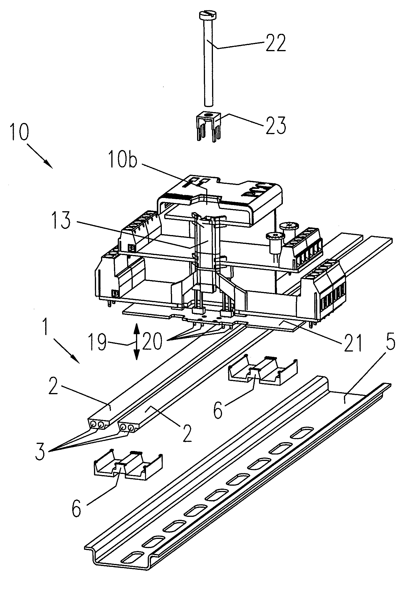
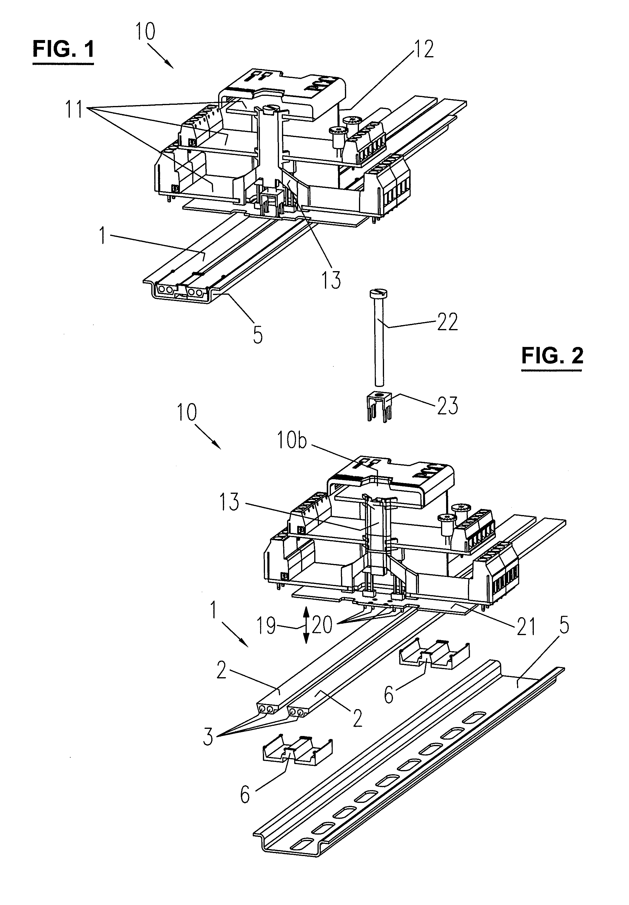
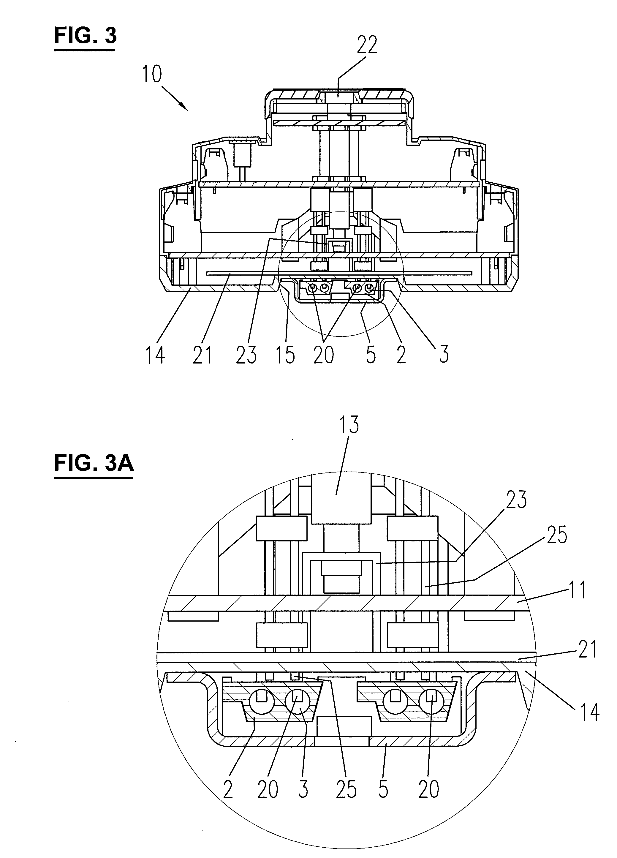
[0011]FIGS. 1 and 2 show a network component, i.e. a part of a network comprising a communication line 1 and a control device 10. The communication line 1 serves for exchanging signals among different control devices and may be configured as a bus (e.g. Profibus, CAN-bus, EIB, etc.), ethernet or in the form of any other line suitable for communication. In the embodiment shown here the communication line 1 comprises two cables. Each cable comprises an insulation jacket 2 which encloses two wires 3 and has an upper and a lower surface, which are substantially flat.

[0012]The communication line 1 runs in a channel of a mounting rail 5. The mounting rail 5 is e.g. a rail according to the norm “EN 60715 DA 38” or any other rail suitable for carrying a communication line 1 and control devices. The mounting rail 5 shown here comprises lateral wings which are arranged adjacent to the channel and holes formed in the channel for attaching the mounting rail 5 to a mounting surface, e.g. a wall,...


PUM


Abstract

The electrical device (10) is configured to be connected electrically to external wires (3), which are enclosed by an insulation material (2). The electrical device includes internal terminals for being connected to the wires (3) and pins (20) for piercing the insulation material (2) and contacting the wires (3). The pins (20) are arranged movably (19) in relation to the internal terminals of the electrical device (10).

Description

FIELD OF THE INVENTION[0001]The present invention relates to an electrical device, which is configured to be connected electrically to external wires enclosed by an insulation material.BACKGROUND OF THE INVENTION[0002]Suitable measures are to be provided for in order to connect the internal terminals of an electrical device to external wires. The wires may be part of a communication line of a network and run e.g. in a channel of a rail on which the electrical device is mounted. It is known to use additional connectors, wires or the like to make such a connection. However, such means make it difficult to arrange the electrical device in a definite position in relation to the wires.SUMMARY OF THE INVENTION[0003]It is an aim of the present invention to provide for an electrical device, which is suitable to be connected to external wires such that the position of the electrical device relative to the wires can be chosen in a flexible manner.[0004]This aim is achieved by an electrical de...

Claims


Application Information

Patent Timeline
IPC IPC(8): H01R4/24H01R13/00
CPCH01R4/2408H01R4/2433H01R25/142H01R13/6658H01R9/2625H01R4/2406
Inventor COSTA, JEAN-PAULSTAEUBLI, THOMAS
Owner SAIA BURGESS CONTROLS
Why Eureka
Try Eureka