Valve for a surgical or medical instrument

Active Publication Date: 2010-05-04
MIALHE CLAUDE
View PDF19 Cites 0 Cited by
  • Summary
  • Abstract
  • Description
  • Claims
  • Application Information

AI Technical Summary

Benefits of technology

[0019]According to one embodiment, the configuration of the valve according to the invention allows it to be operated by an operator using only one hand, the hand which he uses to hold the surgical instrument itself.
[0020]According to a preferred variant, the invention also allows smooth rotational movement of a torsionally deformable element.
[0021]In addition, the cable drive system proposed according to the

Problems solved by technology

This system does not give entire satisfaction, especially because the system used by the operator to transmit the movement

Method used


Image

  • Valve for a surgical or medical instrument
  • Valve for a surgical or medical instrument
  • Valve for a surgical or medical instrument

Examples


Example

[0059]A slide for the gripping means in FIG. 14 is shown on FIG. 15.

DETAILED DESCRIPTION OF THE INVENTION

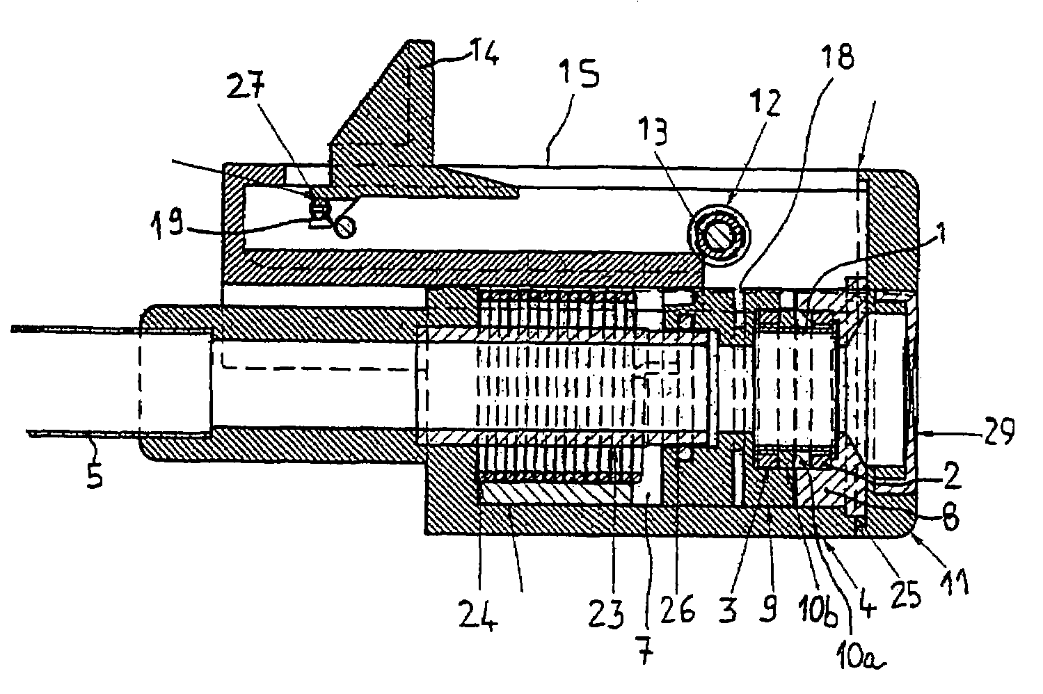
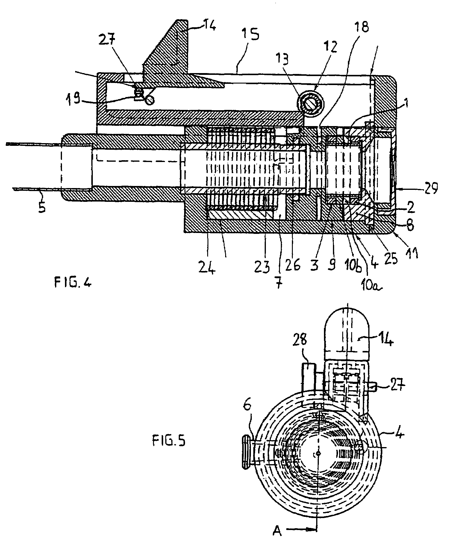
[0060]The valve according to the invention uses the twisting properties of a flexible section 1 of a passage inside the valve.

[0061]This passage extends generally along the length of the valve so as to emerge in tube 5, a distal part of which is used for introduction into the patient's body.

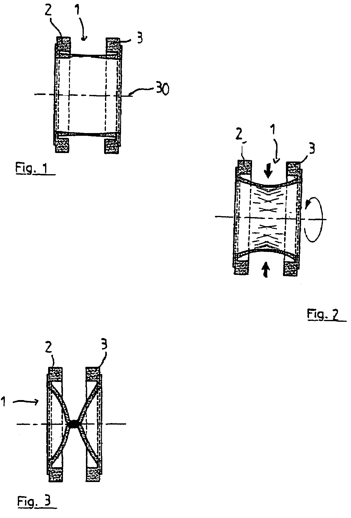
[0062]The flexible section such as is shown on FIGS. 1 to 3 is made up of an appreciably hollow cylindrical form made of a tight and flexible material such as silicone.

[0063]Section 12 in this case includes two ends 2, 3 with an edge which is thicker than the remainder of flexible section 1 so as to constitute elements joining the flexible section to the other parts.

[0064]On FIG. 1, flexible section 1 is not stressed and the central passage is entirely open.

[0065]On FIG. 2, an arrow along the valve axis indicates the start of end 3 rotation and, therefore, the start of flexible section 1 tendi...


PUM


Abstract

A valve for surgical or medical instruments includes a passage that can be at least partially sealed by twisting a flexible section (1) of the passage wall, an element for rotating a mobile end (3) of flexible section (1), characterized in that the actuating element includes a cable for transmitting movement to mobile end (3) of the flexible section. Also described is a surgical or medical instrument including a valve as detailed.

Description

CROSS-REFERENCE TO RELATED APPLICATIONS[0001]The present application claims benefit of priority and incorporates by reference French Application No. 0452874 filed Dec. 6, 2004, U.S. Application 60 / 669,361 file Apr. 8, 2005 and PCT / EP2005 / 056440 filed Dec. 2, 2005.STATEMENT REGARDING FEDERALLY SPONSORED RESEARCH OR DEVELOPMENT[0002]None.THE NAMES OF THE PARTIES TO A JOINT RESEARCH AGREEMENT[0003]None.INCORPORATION-BY-REFERENCE OF MATERIAL SUBMITTED ON A COMPACT DISC[0004]None.BACKGROUND OF THE INVENTION[0005]1. Field of the Invention[0006]This invention concerns a valve for surgical or medical instrument as well as a surgical or medical instrument equipped with the said valve.[0007]The invention will particularly apply to the execution of endovascular introducers.[0008]2. Description of Related Art[0009]However, this field is not exhaustive.[0010]Instruments used as introducers into a patient's body, and in particular for endovascular, including percutaneous and / or transparietal, int...

Claims


Application Information

Patent Timeline
IPC IPC(8): F16K7/04
CPCA61B17/3462A61M39/0613A61M39/288
Inventor MIALHE, CLAUDE
Owner MIALHE CLAUDE
Why Eureka
Try Eureka