Stop control system and method for internal combustion engine

Active Publication Date: 2012-05-24
HONDA MOTOR CO LTD
View PDF3 Cites 2 Cited by
  • Summary
  • Abstract
  • Description
  • Claims
  • Application Information

AI Technical Summary

Benefits of technology

[0026]The invention as claimed in claim 10 is the stop control method as claimed in claim 9, further comprising a step of setting the second predetermined rotational speed according to a state of the engine 3, and a step of setting the first predetermined rotational speed according to the set second predetermined rotational speed.
[0027]With this configuration, it is possible to obtain the same advantageous effects as provided by the above-described claim 2.
[0028]The invention as claimed in claim 11 is the stop control method as claimed in claim 9, further comprising a step of setting the second predetermined opening degree according to a state of the engine 3, and a step of setting the first predetermined rotational speed according to the set second predetermined opening degree.
[0029]With this configuration, it is poss

Problems solved by technology

This is because when the engine is stopped in a state where valve overlap occurs, exhaust gases in an exhaust passage flow back into an intake passage via the exhaust valv

Method used


Image

  • Stop control system and method for internal combustion engine
  • Stop control system and method for internal combustion engine
  • Stop control system and method for internal combustion engine

Examples


first embodiment

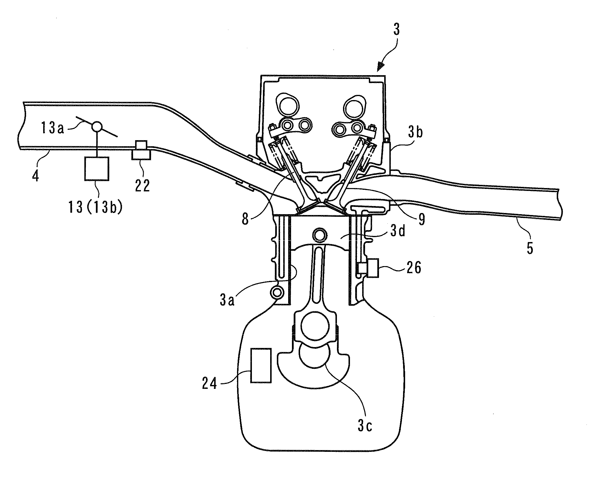
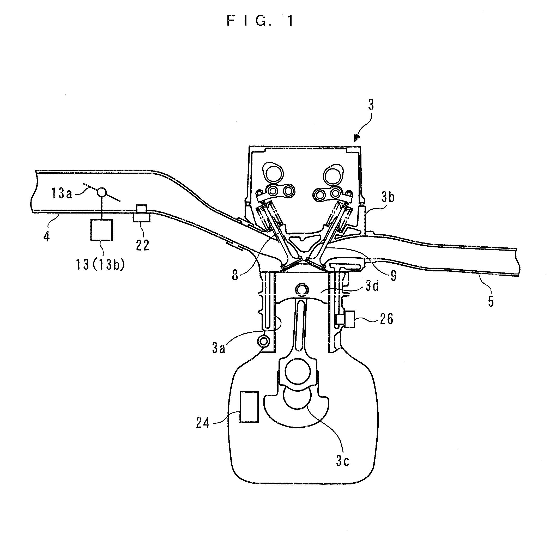
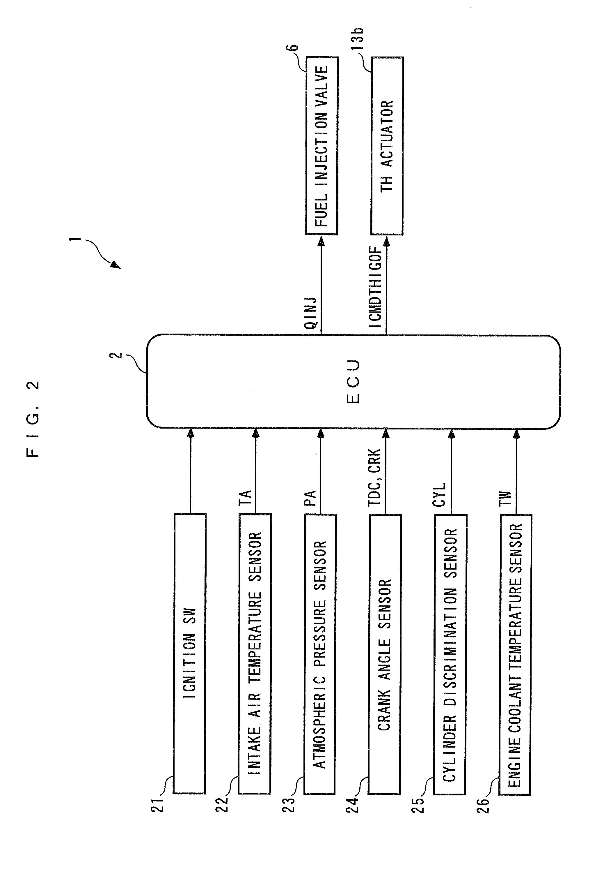
[0085]Next, stop control of the engine 3 executed by the ECU 2, will be described with reference to FIGS. 4 to 14. The stop control is for controlling the stop position of the piston 3d to a predetermined position at which no valve overlap occurs in which the intake valve 8 and the exhaust valve 9 open at the same time, by controlling the throttle valve 13a toward an open side when the engine speed NE becomes lower than a stop control start rotational speed NEIGOFTH after the ignition switch 21 has been turned off, to thereby control the engine speed NE in the final compression stroke immediately before stoppage of the piston 3d (final compression stroke rotational speed NEPRSFTGT) to a predetermined reference value.

[0086]FIG. 4 shows a process for setting a target stop control start rotational speed NEICOFREFX. The present process and processes described hereinafter are executed in synchronism with generation of the CYL signal. The present process is for setting a target value of ...

second embodiment

[0159]FIG. 19 shows an example of an operation obtained by a stop control process of the engine 3 according to the above-described In a case indicated by solid lines in the figure, when the ignition switch 21 is turned off, the target opening degree ICMDTHIGOF is set to 0, whereby the throttle valve opening ATH is controlled such that the throttle valve 13a is fully closed, and the intake pressure PBA is reduced. After that, when the engine speed NE becomes lower than the first stage control start rotational speed NEICOFPRE, the first stage control is started, and further when the engine speed NE becomes lower than the corrected target stop control start rotational speed NEICOFREFN, the second stage control is started. At this time, the intake pressure PBA has increased up to the desired initial value PBAREF.

[0160]In contrast, in a case indicated by broken lines in the figure, the corrected target stop control start rotational speed NEICOFREFN is set to a smaller value than in the ...

third embodiment

[0203]Note that in the above-described third embodiment, the first stage control start rotational speed NEICOFPRE is a fixed value, the first stage control start rotational speed NEICOFPRE may be corrected and set using the atmospheric pressure PA and the intake air temperature TA. Specifically, first, a map shown in FIG. 10 is searched according to the atmospheric pressure PA to determine a map value DNEICOFPA, whereby the map value DNEICOFPA is set as the setting PA correction term dneicofpax, and a map shown in FIG. 11 is searched according to the intake air temperature TA to determine a map value DNEICOFTA, whereby the map value DNEICOFTA is set as the setting TA correction term dneicoftax. Then, the second predetermined opening degree ICMDOF2 is calculated using a basic value NEICOFPREB of the first stage control start rotational speed and the setting PA correction term dneicofpax and the setting TA correction term dneicoftax, by the following equation (15):

NEICOFPRE=NEICOFPREB...


PUM


Abstract

A stop control system for an internal combustion engine, which is capable of accurately stopping a piston at a predetermined position during stoppage of the engine while preventing occurrence of untoward noise and vibration. After stopping the engine 3, the stop control system 1 for the engine 3 according to the present invention executes a first stage control (step 34) in which a throttle valve 13a is controlled to a first stage control target opening degree ICMDOFPRE smaller than a second predetermined opening degree ICMDOF2, in order to stop the piston at the predetermined position, before executing a second stage control (step 42) in which the throttle valve 13a is controlled to the second predetermined opening degree ICMDOF2. Further, the stop control system 1 stabilizes initial conditions at the start of the second stage control by setting a first stage control start rotational speed NEICOFPRE and a first stage control target opening degree ICMDOFPRE according to a change in a corrected target stop control start rotational speed NEICOFREFN (steps 71 and 85).

Description

TECHNICAL FIELD[0001]The present invention relates to a stop control system and method for an internal combustion engine, for controlling a stop position of a piston to a predetermined position by controlling an intake air amount during stoppage of the engine.BACKGROUND ART[0002]When stopping the engine, it is desirable that the piston is caused to stop at a predetermined position that causes no valve overlap in which an intake valve and an exhaust valve are both opened. This is because when the engine is stopped in a state where valve overlap occurs, exhaust gases in an exhaust passage flow back into an intake passage via the exhaust valve and the intake valve during stoppage of the engine, which can result in degraded engine startability at the following start of the engine and increased exhaust emissions.[0003]On the other hand, conventionally, as a control system for controlling the opening degree of a throttle valve during stoppage of the engine, one disclosed in Patent Literat...

Claims


Application Information

Patent Timeline
IPC IPC(8): F02D17/04
CPCF02D41/0002F02D41/042F02N2019/008F02N19/005F02D41/10
Inventor HOZUMI, TOMOHARUMITSUI, ATSUSHIAOKI, TAKESHIYATANI, HIROSHIIMAMURA, KAZUHIKO
Owner HONDA MOTOR CO LTD
Why Eureka
Try Eureka