Spool valve

Active Publication Date: 2017-07-27
NTN CORP
View PDF8 Cites 13 Cited by
  • Summary
  • Abstract
  • Description
  • Claims
  • Application Information

AI Technical Summary

Benefits of technology

[0026]According to the present invention, since the spool is axially moved by actuating a ball-screw by driving an electric motor, the spool can be moved a longer distance than the spool of a conventional spool valve in which the spool is moved by a solenoid. This makes it possible to increase the degrees of opening of the various ports of the spool valve, including the input port, and thus to increase the sectional areas of the oil passages connected to the respective ports, which in turn improves the responsiveness of the object to be hydraulically controlled, such as a V-belt type contin

Problems solved by technology

Since oil cannot be supplied at a high flow rate through such narrow oil supply passages, the clutch as the object to be hydraulically controlled cannot be controlled

Method used


Image

  • Spool valve
  • Spool valve
  • Spool valve

Examples


Example

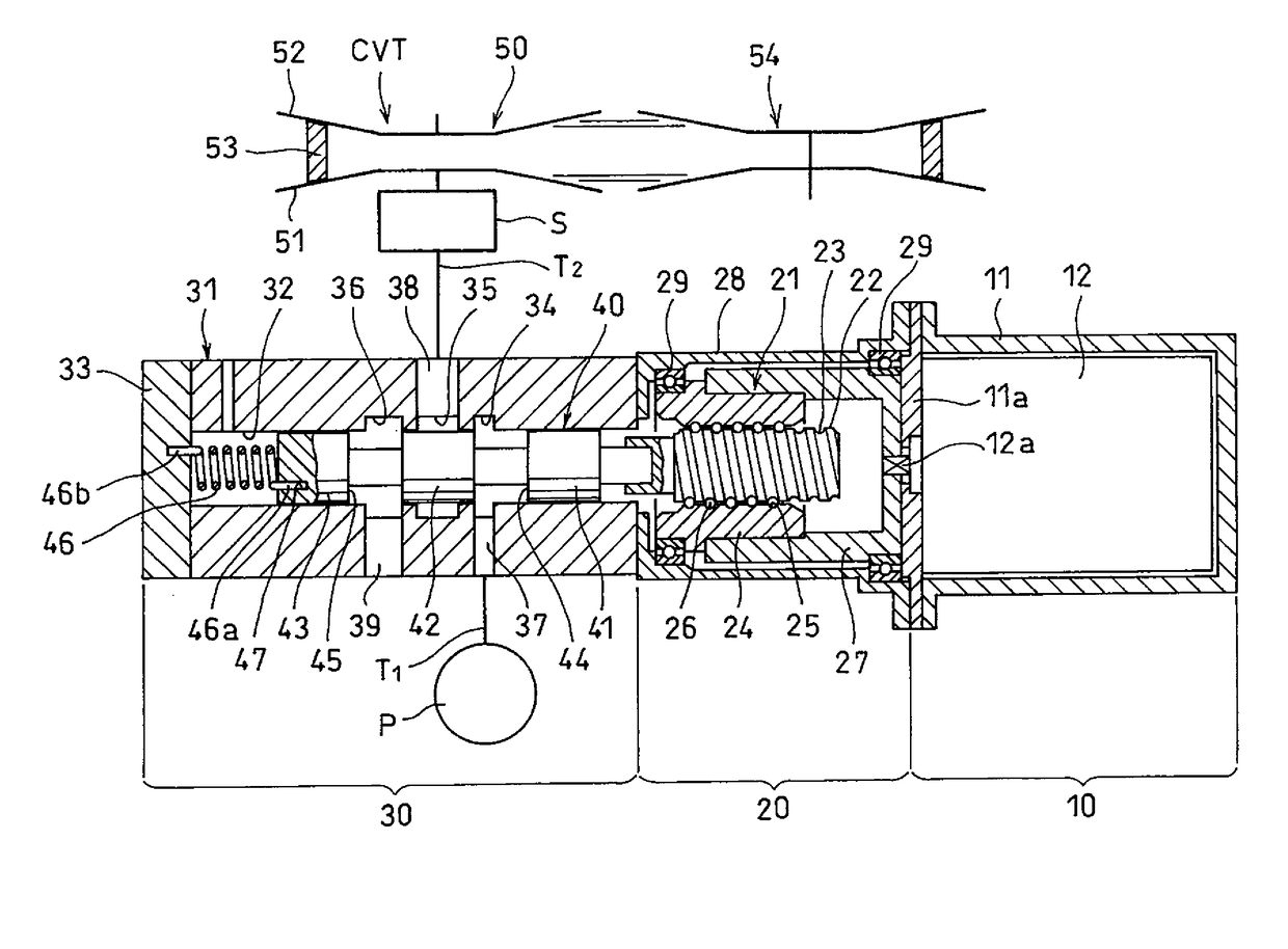
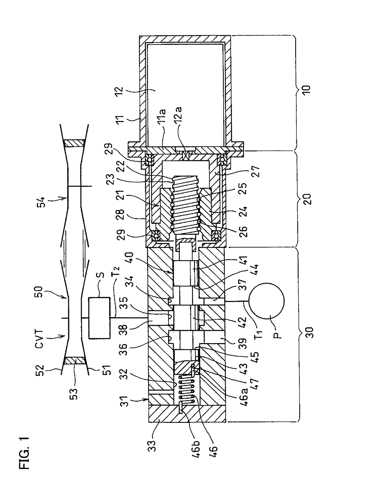
[0044]Embodiments of the present invention are now described with reference to the drawings. FIG. 1 shows a spool valve of one embodiment which comprises an electric motor section 10, a motion converter mechanism section 20 configured to covert a rotary motion to a linear motion, and a hydraulic control section 30.

[0045]The electric motor section 10 comprises a motor case 11, and an electric motor 12 mounted in the motor case 11. The electric motor 123 has a rotary shaft 12a extending through an end plate 11a of the motor case 11, and protruding into the below-described nut case 28 connected to an end of the motor case 11.

[0046]The motion converter mechanism section 20 includes a ball-screw 21, and a nut case 28 covering the ball-screw 21. The ball-screw 21 includes a threaded shaft 22 having a thread groove 23 in the outer periphery thereof, a nut 24 fitted around the threaded shaft 22, and balls 26 disposed between a thread groove 25 formed in the inner periphery of the nut 24 and...


PUM


Abstract

A spool valve is provided which improves the responsiveness of the object to be hydraulically controlled, such as a V-belt type continuously variable transmission, and which improves the overall safety. The spool valve includes a spool inserted in a spool insertion hole formed in a valve body, The spool is moved by an electric motor via a ball-screw to a first position where the input port communicates with the output port, while the output port is not in communication with the drain port, and to a second position where the input port is not in communication with the output port, while the output port communicates with the drain port.

Description

TECHNICAL FIELD[0001]This invention relates to a spool valve used when hydraulically controlling a cylinder for changing the speed ratio of a V-belt type continuously variable transmission, or when hydraulically controlling a clutch mounted in an automatic transmission.BACKGROUND ART[0002]The below-identified Patent document 1 discloses a conventional spool valve used when hydraulically controlling a clutch mounted in an automatic transmission and configured to change the speed ratio of the transmission. This spool valve includes a sleeve formed with an input port, an output port, a drain port, and a feedback port; and a spool slidably inserted in the sleeve, and configured to be moved, by a driving member, to a first position where the spool allows communication between the input port and the output port, while prohibiting communication between the output port and the drain port, and to a second position where the spool prohibits communication between the input port and the output ...

Claims


Application Information

Patent Timeline
IPC IPC(8): F16H61/662B60W10/101F15B13/04F16K11/065B60W10/04
CPCF16H61/66259F16K11/065F16H61/66F15B13/0402B60W10/101B60W10/04F16K31/50F16K31/53F16K11/07F16K31/04F16H61/0251F16H2025/2087F16H2061/0253F16H63/062F16H63/065F16H25/2204F16H2025/204F16H2063/3063
Inventor SASANUMA, KYOHEINORIMATSU, TAKAYUKIHATTORI, NAOSHISAITO, TAKAHIDEKAWAMURA, HIROSHI
Owner NTN CORP
Why Eureka
Try Eureka