Pneumatic booster

Active Publication Date: 2005-05-31
HITACHI LTD
View PDF13 Cites 2 Cited by
  • Summary
  • Abstract
  • Description
  • Claims
  • Application Information

AI Technical Summary

Benefits of technology

[0026]With this arrangement, when an input force is applied to the input rod at a high rate, the speed of the plunger moved by the input rod and the speed of the valve body moved by a thrust force of the power piston become different. Due to a difference in speed between t

Problems solved by technology

Due to a difference in speed between the plunger and the valve body, an amount of movement of the plunger relat

Method used


Image

  • Pneumatic booster
  • Pneumatic booster
  • Pneumatic booster

Examples


first embodiment

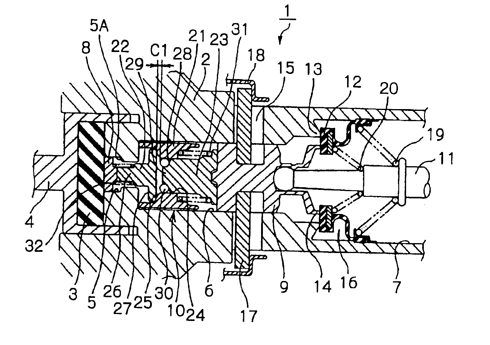
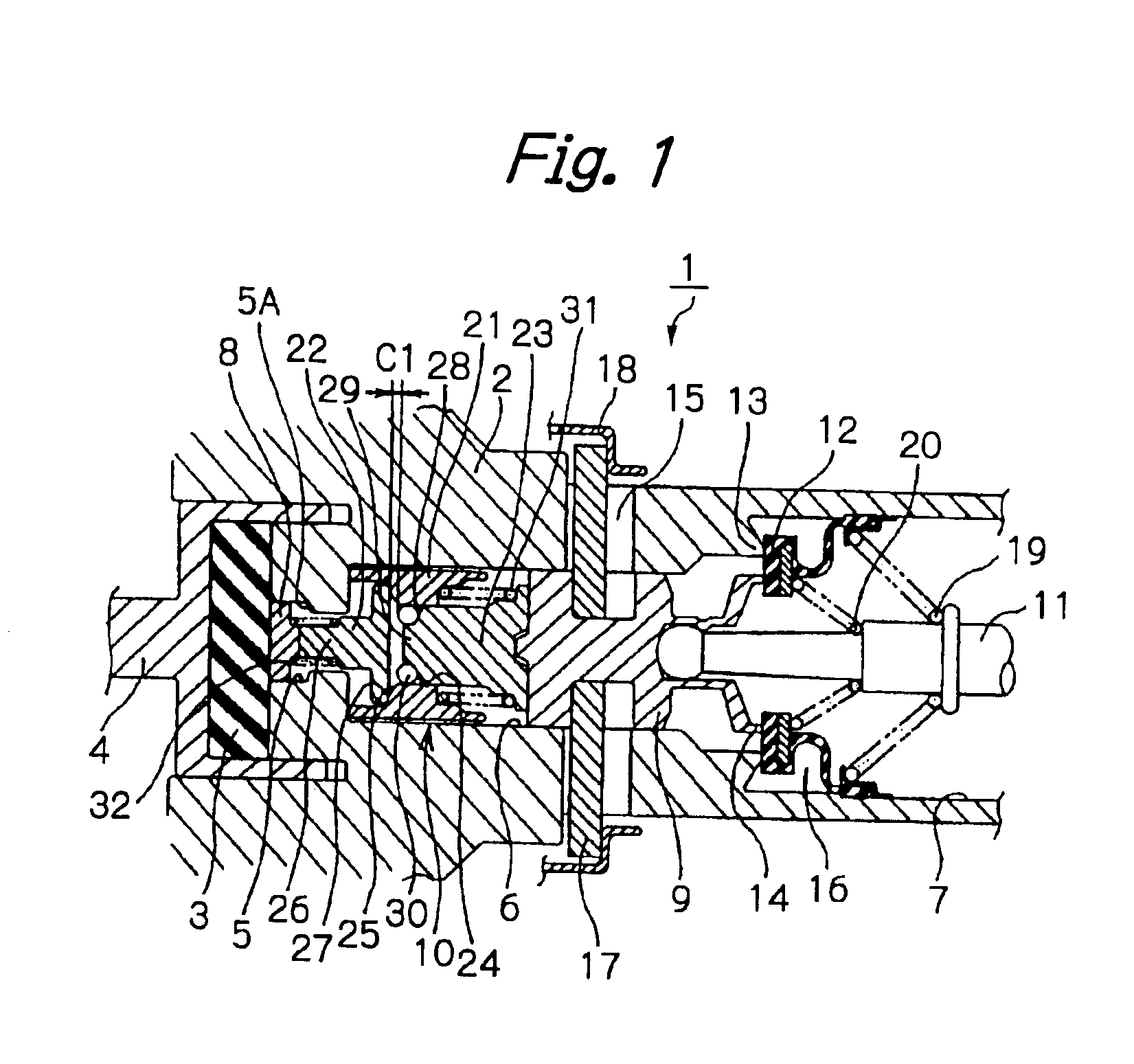
[0056]First, the present invention is described, referring to FIGS. 1 to 4 and FIG. 7. FIG. 1 shows an inside of a valve body 2, which is an essential part of a pneumatic booster 1 in this embodiment. As is the case with the above-mentioned conventional pneumatic booster, the pneumatic booster 1 comprises a housing (not shown) divided into a constant pressure chamber and a variable pressure chamber by a power piston. The valve body 2, which is in a generally cylindrical form, has one end portion connected to the power piston. The other end portion of the valve body 2 is slidably and gas-tightly inserted through a rear wall of the housing and extends to the outside. The one end portion of the valve body 2 is also connected to an output rod 4 through a reaction disk 3 (a reaction member). A forward end portion of the output rod 4 is connected to a piston provided in a master cylinder (not shown) attached to a front wall of the housing.

[0057]The inside of the valve body 2 has a stepped...

second embodiment

[0085]The pneumatic booster in the second embodiment is arranged in the above-mentioned manner. An operation of this pneumatic booster is described below.

[0086]During normal braking, the sleeve 59 is located at a position such that it abuts against the flange portion 27 of the reaction rod 22, under a spring force of the spring 61. The elastic member 57 is contained in a space sealed by the inner circumferential surface of the sleeve 59. In this state, a reduction in an axial dimension L1 of the elastic member 57 resulting from compression of the elastic member 57 depends on volume elasticity of the elastic member 57. Therefore, the modulus of elasticity of the elastic member 57 is high, so that an axial dimension of the brake assisting mechanism 55 is substantially unchanged. Therefore, as is the case with the first embodiment, atmospheric air is introduced into the variable pressure chamber by movement of the plunger 9 due to the input rod 11, and a thrust force generated in the p...


PUM


Abstract

A valve body 2 is connected to a power piston, which divides a housing into a constant pressure chamber (negative pressure) and a variable pressure chamber. In the valve body 2, there is provided a brake assisting mechanism 10 between a reaction disk 3 and a plunger 9. A poppet seal 12 is opened by movement of the plunger 9, to thereby introduce atmospheric air into the variable pressure chamber and generate a thrust force in the power piston. During rapid braking, a plunger rod 23 advances relative to a sleeve 21, and balls 30 shift outward and the plunger rod 23 directly abuts against a reaction rod 22, resulting in contraction of the brake assisting mechanism 10. Therefore, the amount of movement of the plunger 9 can be increased without being affected by a reaction force from the reaction disk 3, thus enabling rapid development of servo power.

Description

BACKGROUND OF THE INVENTION[0001]The present invention relates to a pneumatic booster attached to a brake apparatus for a vehicle, such as an automobile.[0002]In general, a pneumatic booster is attached to a brake apparatus for an automobile, so as to generate a large braking force. As a pneumatic booster, generally, there has been known a pneumatic booster in which a housing is divided, by means of a power piston, into a constant pressure chamber (which is maintained at negative pressure under an intake pressure of an engine) and a variable pressure chamber. A valve body is connected to the power piston, and a plunger provided inside the valve body is moved by means of an input rod, to thereby introduce atmospheric air (positive pressure) into the variable pressure chamber, thus generating a pressure differential between the constant pressure chamber and the variable pressure chamber. A thrust force generated in the power piston due to the pressure differential is applied through a...

Claims


Application Information

Patent Timeline
IPC IPC(8): B60T13/52B60T13/57B60T13/575B60T13/573B60T13/56
CPCB60T13/575B60T13/57
Inventor TAKAYAMA, TOSHIOENDO, MITSUHIROTAKAHASHI, TETSUYAWATANABE, SHUZONAKAMURA, TADAAKI
Owner HITACHI LTD
Why Eureka
Try Eureka