

Vehicle air conditioner with front air passage and rear air passage
- Summary
- Abstract
- Description
- Claims
- Application Information
AI Technical Summary
Benefits of technology
Problems solved by technology
Method used
Image

Examples
first embodiment
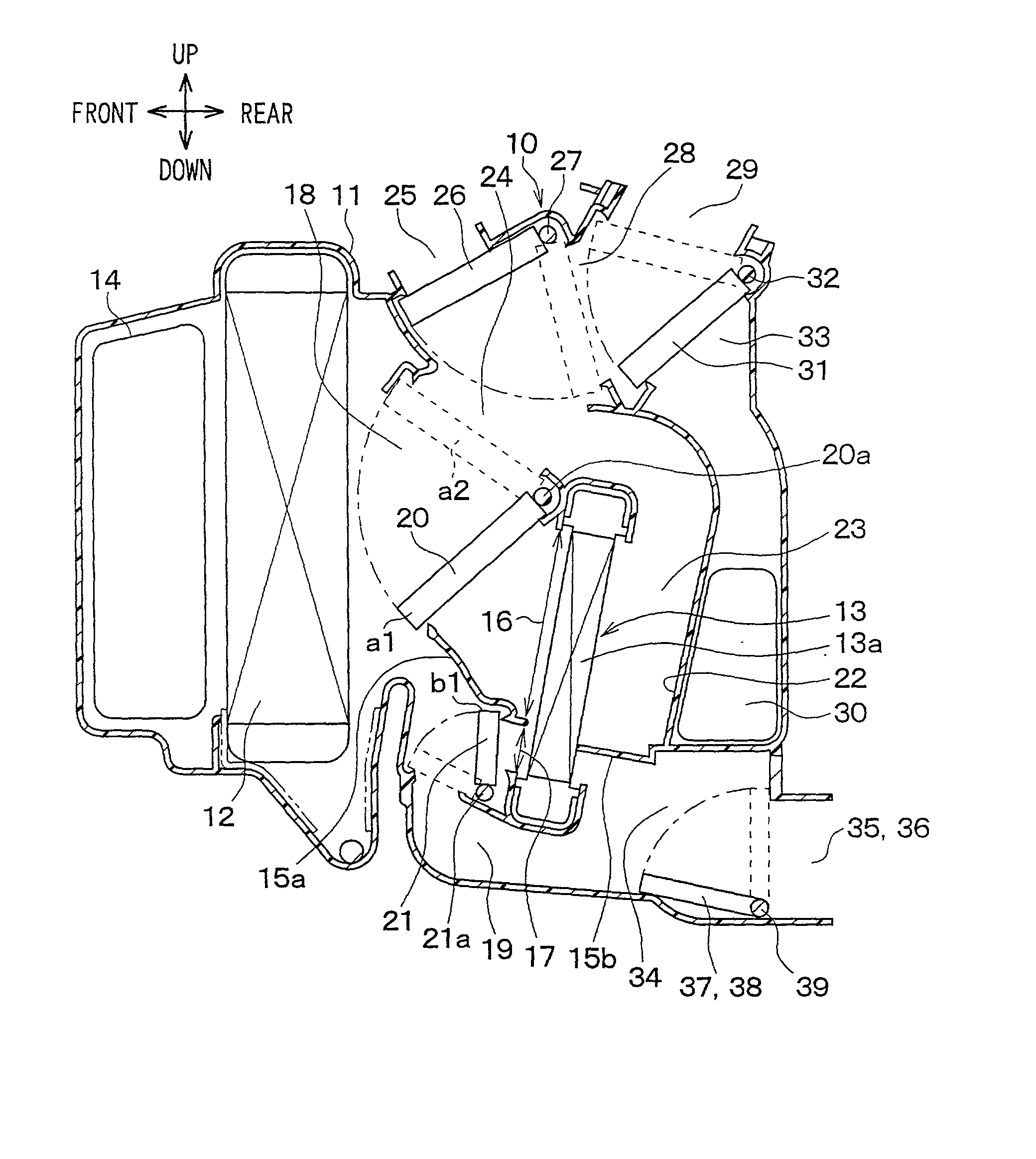
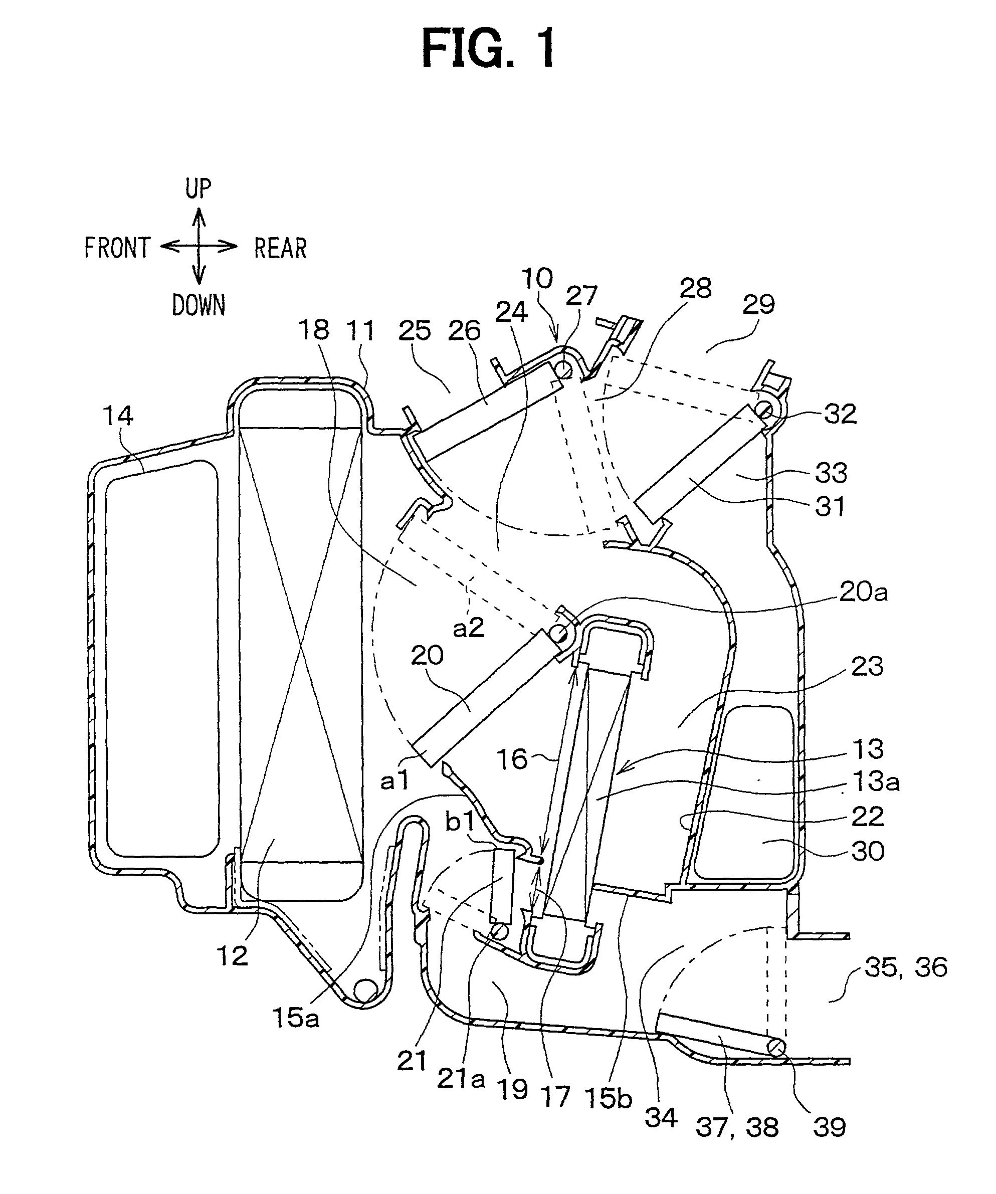
[0024] A first preferred embodiment of the present invention will be now described with reference to FIGS. 1-6. In a vehicle air conditioner a ventilation system includes an air-conditioning unit 10 shown in FIG. 1, and a blower unit 1 (see FIG. 2) for blowing air into the air-conditioning unit 10.
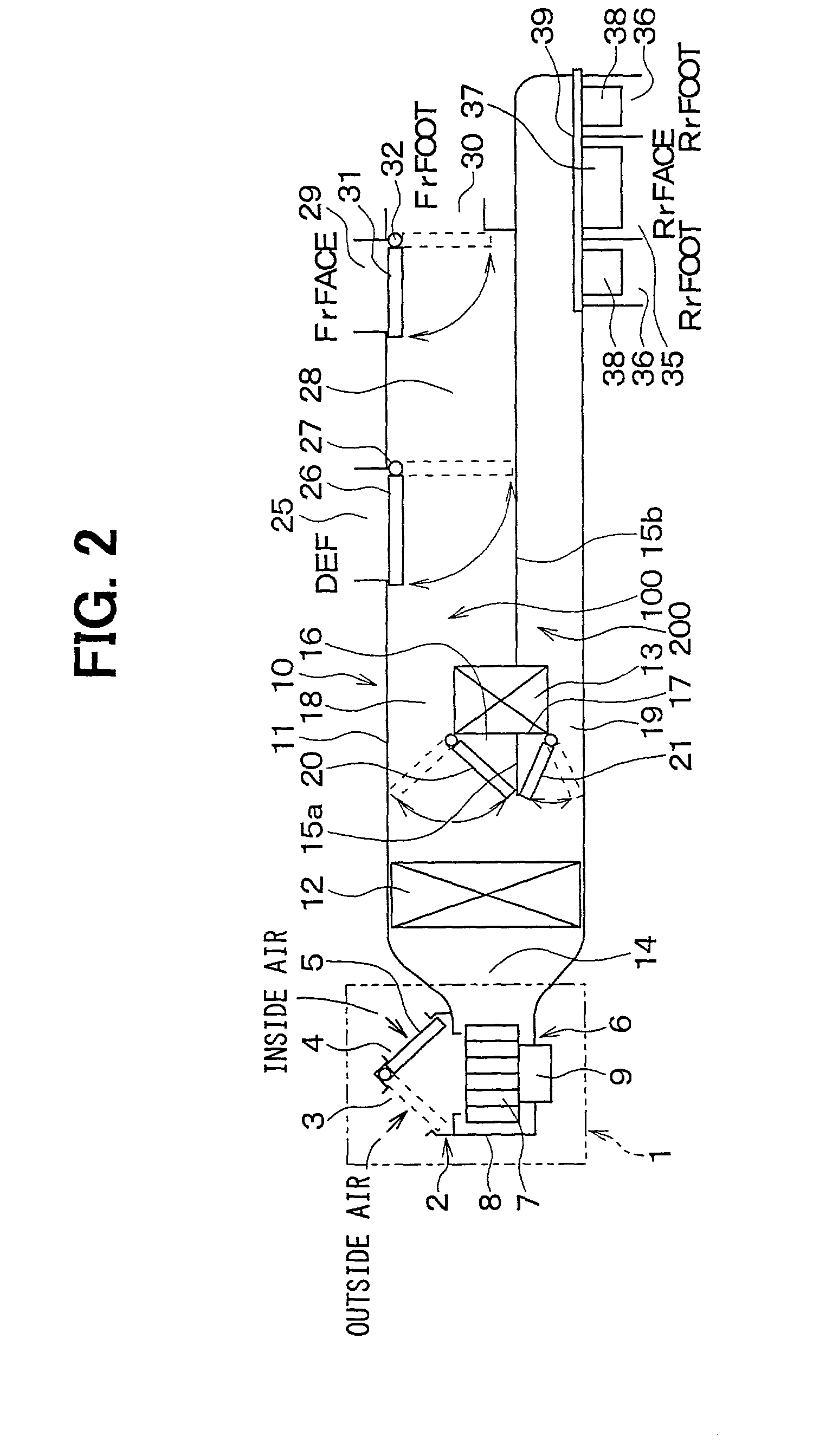
[0025] The blower unit 1 is disposed in a passenger compartment below an instrument panel (not shown) to be offset from a center portion to a front-passenger's seat side in a vehicle right-left direction (width direction). The blower unit 1 includes an inside / outside air switching box 2. The inside / outside air switching box 2 has an outside air suction port 3, an inside air suction port 4, and an inside / outside switching door (switching door) 5 for selectively opening and closing the suction ports 3, 4. Outside air (air outside the passenger compartment) is sucked into the inside / outside air switching box 2 through the outside air suction port 3, and inside air (air inside the passenger c...
second embodiment
[0079] A second preferred embodiment of the present invention will be now described with reference to FIG. 7. In the second embodiment, the correction voltage of the blower voltage BLW is changed according to an open degree of the front air-mixing door 20.
[0080] The correction control (step S10) according to the second embodiment is specifically indicated by the flow diagram shown in FIG. 7. In FIG. 7, steps similar to those shown in FIG. 6 are indicated by the same reference numbers, and the explanation of thereof is omitted. At step S102 in FIG. 7, when the state, immediately after the closing state of the rear openings 35, 36 is changed to the opening state of the rear openings 35, 36, is determined, the control program proceeds to step S109. At step S109, it is determined whether or not an operation position of the front air-mixing door 20 is in a large open degree area (i.e., high temperature area at a maximum heating side). For example, when the operation position of the front...
third embodiment
[0089] A third preferred embodiment of the present invention will be now described with reference to FIG. 8. In the third embodiment, the correction voltage of the blower voltage BLW is changed according to the blower voltage BLW before the correction. As indicated by the solid line X in FIG. 5, the blower voltage BLW before the correction is determined by the front target temperature TAOf.
[0090] A blower correction control according to the third embodiment is described in detail in accordance with the flow diagram shown in FIG. 8. At step S102 in FIG. 7, when the state, immediately after the closing state of the rear openings 35, 36 is changed to the opening state of the rear openings 35, 36, is determined, the control program proceeds to step S112. At step S112, it is determined whether or not the blower voltage BLW before the correction is smaller than a first predetermined voltage BLW1 (e.g., 5 V). In FIG. 5, for example, a minimum voltage V2 of the blower voltage BLW is 4 V, an...
PUM
 Abstract
Description
Claims
Application Information