
Noninvasive methods, apparatus, kits, and systems for intraoperative position and length determination

Inactive Publication Date: 2007-01-25
OSTEOMETRIX
View PDF31 Cites 56 Cited by
  • Summary
  • Abstract
  • Description
  • Claims
  • Application Information

AI Technical Summary

Benefits of technology

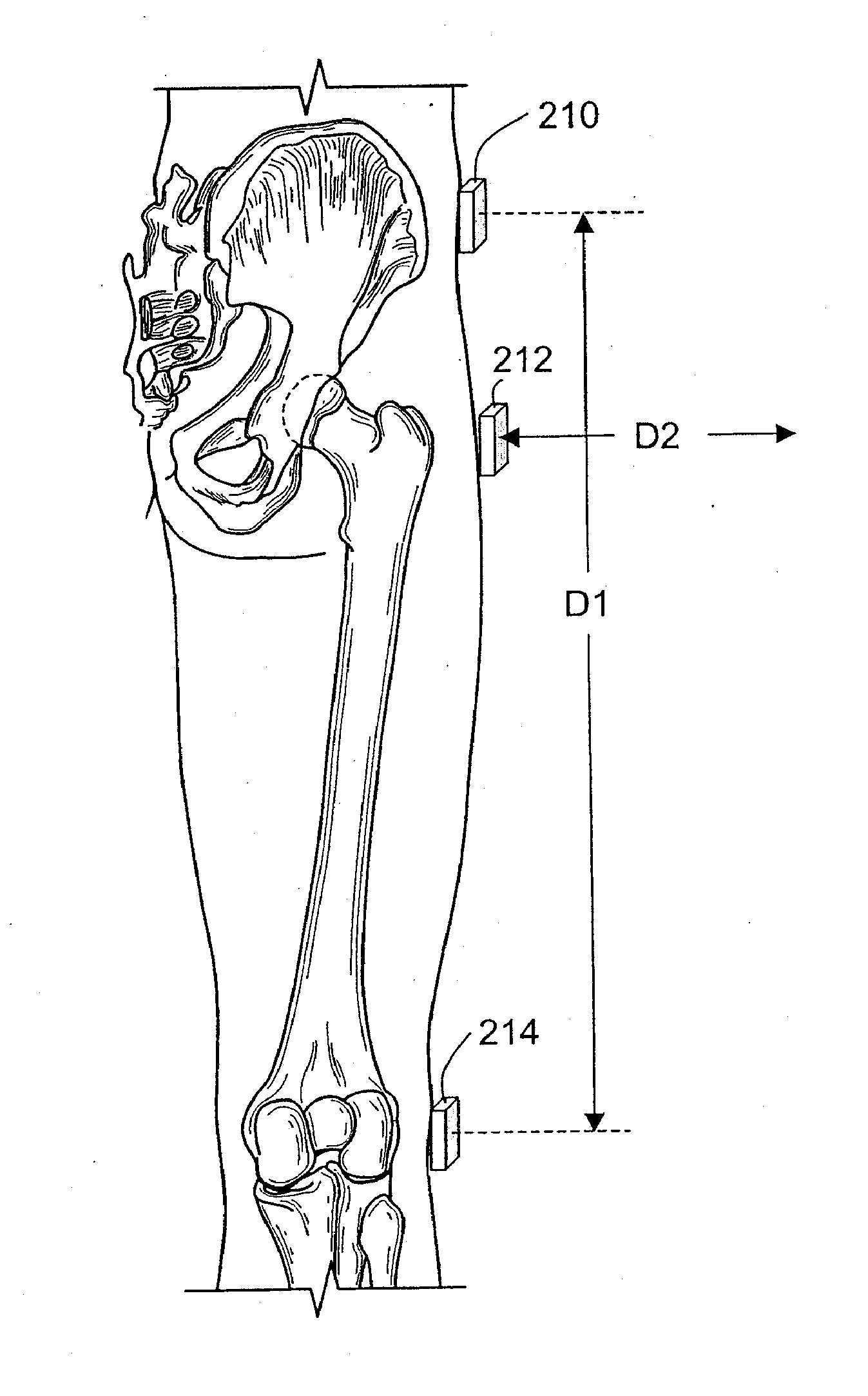
[0015] The present invention solves these and other needs in the art by using magnetic field sources, typically permanent magnets, to provide simple, inexpensive, disposable markers for desired anatomic locations; the location of the magnetic markers is readily sensed, without dedicated communication links, using magnetic field sensing apparatus positioned external to the patient.
[0018] Using the methods, systems, and apparatus of the present invention during total hip replacement surgery, the leg length achieved intraoperatively upon implantation of one or more trial prostheses can readily be compared to the preoperative leg length, thus facilitating selection of a prosthesis that best equalizes the length of the involved and uninvolved legs. INCORPORATION BY REFERENCE

Problems solved by technology

Differences in leg length affects gait, may cause instability of the hip joint, and may exacerbate pain.
In addition, the surgeon's failure to equalize or maintain leg length during THR is readily noticeable, and is a frequent source of patient dissatisfaction with THR surgery.
The methods and apparatus currently available to measure leg length during THR surgery, however, are typically inaccurate, often invasive, and at times complex.
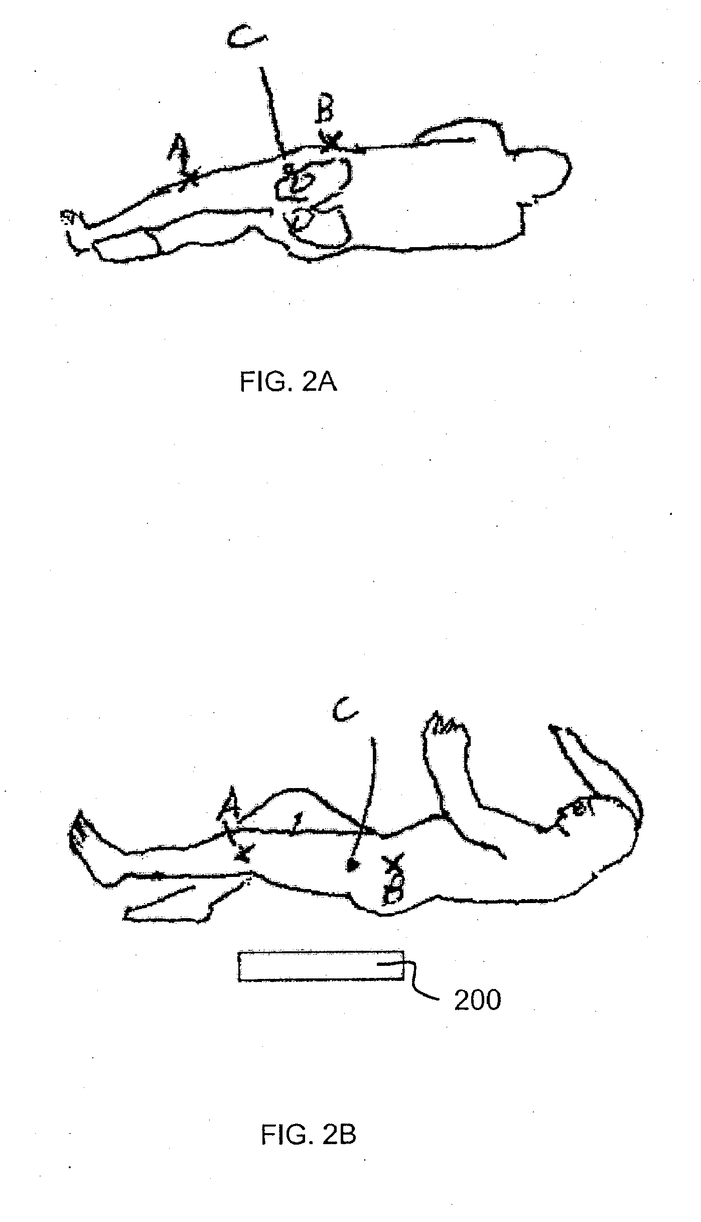
Simple, direct comparison of leg lengths by visually comparing the positions of the medial malleoli of the ankles is not a valid measurement when patients are in the lateral decubitus position, the position used by almost all surgeons, since the pelvis is oblique and not level in this position.
The “shuck” test, in which the surgeon pulls longitudinally on the leg to check how far the joint may be distracted with a trial implant in place, merely assesses the tightness of the soft tissues around the hip joint and is often inaccurate for assessing leg length.
Whether performed by mechanical device or by laser, the measurement between the pelvic pin and femoral reference point is frequently inaccurate, in part due to the difficulty of fixedly securing the pin to the ilium for the duration of the procedure.
Each of the above-described approaches suffers from one or more of inaccuracy, invasiveness, and mechanical and / or computational complexity.

Method used


Image

  • Noninvasive methods, apparatus, kits, and systems for intraoperative position and length determination
  • Noninvasive methods, apparatus, kits, and systems for intraoperative position and length determination
  • Noninvasive methods, apparatus, kits, and systems for intraoperative position and length determination

Examples


Embodiment Construction

[0029] While preferred embodiments of the present invention have been shown and described herein, it will be obvious to those skilled in the art that such embodiments are provided by way of example only. Numerous variations, changes, and substitutions will now occur to those skilled in the art without departing from the invention. It should be understood that various alternatives to the embodiments of the invention described herein may be employed in practicing the invention. It is intended that the following claims define the scope of the invention and that methods and structures within the scope of these claims and their equivalents be covered thereby.

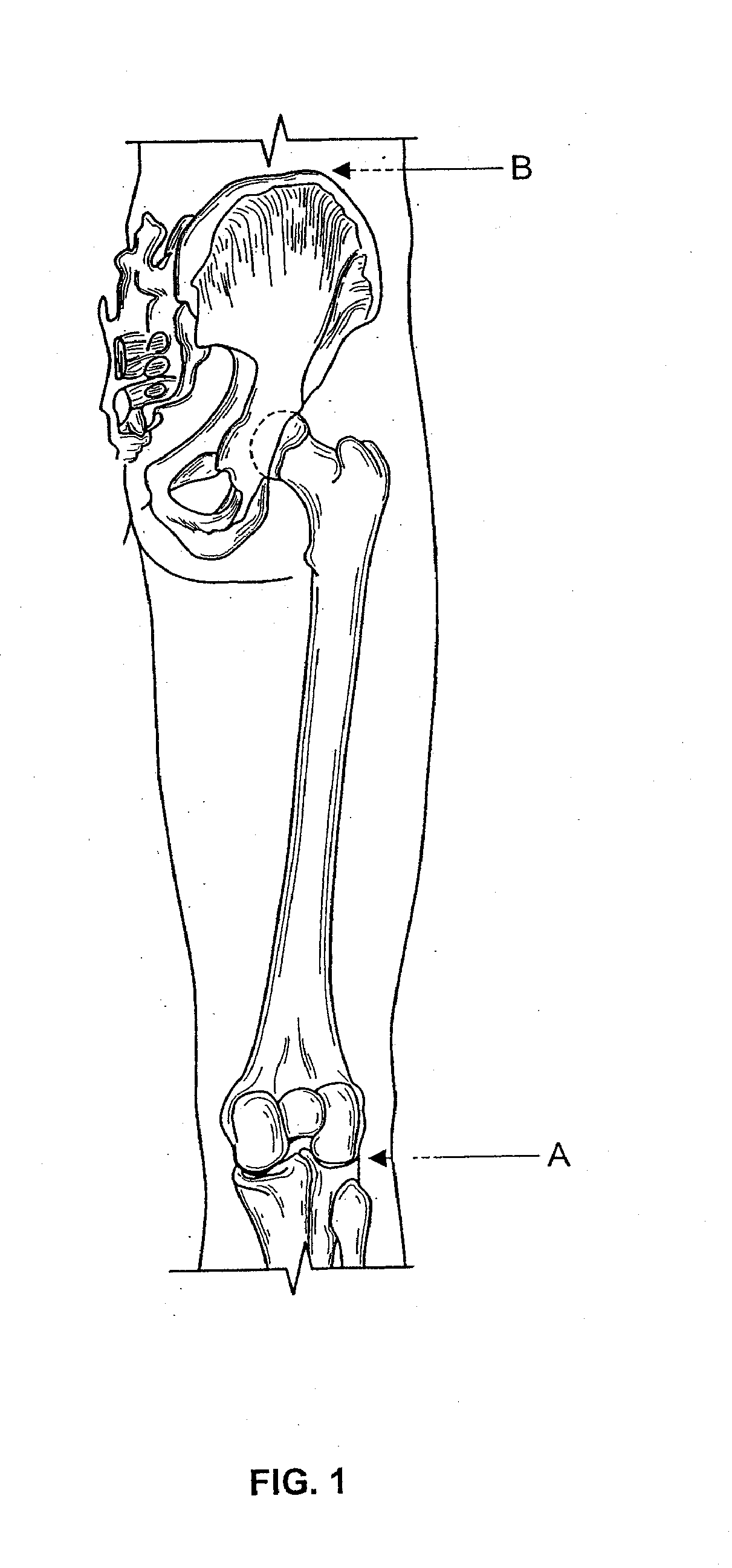
[0030] The present invention applies magnetic sensing technology to monitor the spatial position of desired anatomic locations and to determine the distance between two or more such anatomic locations during surgery.

[0031] In a first aspect, the invention provides methods for determining the spatial position of at least one anatomi...


PUM


Abstract

Methods, apparatus, kits and systems are presented for determining the intraoperative position of at least a first anatomic location of a surgical patient and optionally for measuring the distance between at least first and second anatomic locations of a surgical patient.

Description

CROSS-REFERENCE [0001] This application claims the benefit of U.S. Provisional Application No. 60 / 658,100, filed Mar. 2, 2005, which is incorporated herein by reference in its entirety.BACKGROUND OF THE INVENTION [0002] Total hip replacement surgery (THR), also known as total hip arthroplasty, was introduced into clinical practice over thirty years ago and is now performed nearly 250,000 times a year in the United States to relieve pain and improve function in patients who have severe arthritis of the hip joint. [0003] The majority of patients undergoing THR enter surgery with unequal leg lengths, with the affected leg shorter than the normal leg due to loss of the hip joint articular cartilage and erosion of bone from the femoral head due to the arthritic process. Differences in leg length affects gait, may cause instability of the hip joint, and may exacerbate pain. The usual preoperative leg length discrepancy in patients undergoing THR ranges between 4 and 10 mm, but on rare occ...

Claims


Application Information

Patent Timeline
IPC IPC(8): A61N2/00
CPCA61B5/083A61B5/4504A61N2/00A61N1/08A61B5/4528
Inventor WOOLSON, STEVEN T.RADKE, JOHN C.
Owner OSTEOMETRIX
Learn More