Interrupted, vertical flow testing device

a testing device and vertical flow technology, applied in the direction of instruments, chemical methods analysis, analysis using chemical indicators, etc., can solve the problems of no practical rapid diagnostic testing technique for use of confirmatory rapid diagnostic testing, type of assays taking days, if not weeks, etc., to achieve rapid and accurate results, simple and inexpensive disposable instruments, and safe manipulation

Inactive Publication Date: 2005-07-28
DNT SCI RES
View PDF7 Cites 19 Cited by
  • Summary
  • Abstract
  • Description
  • Claims
  • Application Information

AI Technical Summary

Benefits of technology

[0004] The principal and secondary objects of the invention are to provide a device to rapidly and accurately conduct an immunoassay flow through test that can instantly provide a detection, analysis and confirmation of HIV infection by way of a simple, inexpensive and disposable instrument that can be manipulated safely by a relatively low skill person. An additional goal is to maintain the benefit of the dry chemistry, such as in Lateral Flow test method for an economically prolonged room temperature shelf life of at least 24 months.
[0006] A supply of aqueous buffer solution is held in a sealed vessel until the sample specimen has been introduced into the device and the cap has been closed. A prong in the undersurface of the cap punctures a membrane sealing the upper opening of the vessel allowing the buffer solution to be dispensed into the first chamber under atmospheric pressure. A pad at the bottom of the second chamber in contact with a lower part of the strips absorbs the excess wash buffer that has not been retained by the strip. The strips can be positioned in an incline rather than straight vertical position in order to reduce the height of the device. The flow out of the incubation reservoir and into the strip is prompted by a combination of capillarity, gravity and siphoning action forces.

Problems solved by technology

Due to its multi-step manipulation and verification phases, this type of assay takes days, if not weeks.
There is no practical confirmatory rapid diagnostic testing technique for use in a Point-of-Care setting, available in the market place today.

Method used


Image

  • Interrupted, vertical flow testing device
  • Interrupted, vertical flow testing device

Examples


Embodiment Construction

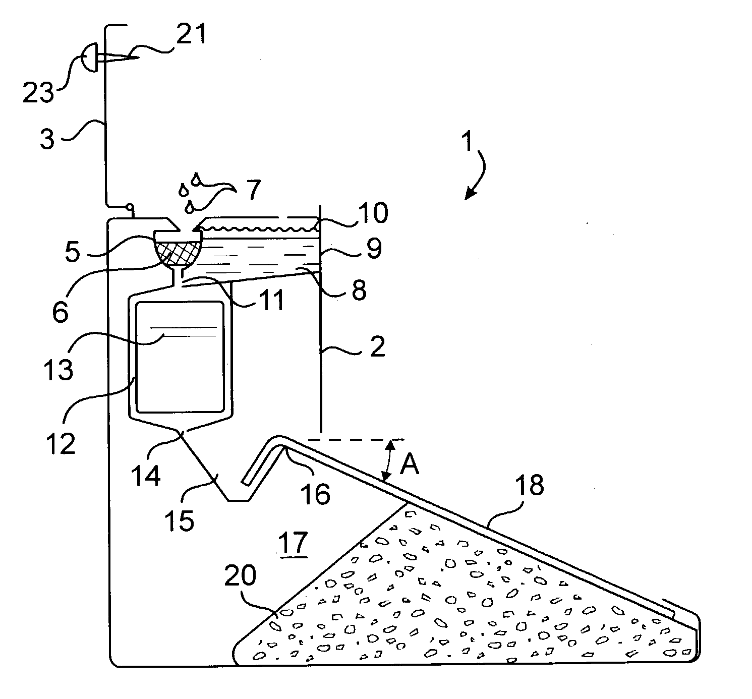
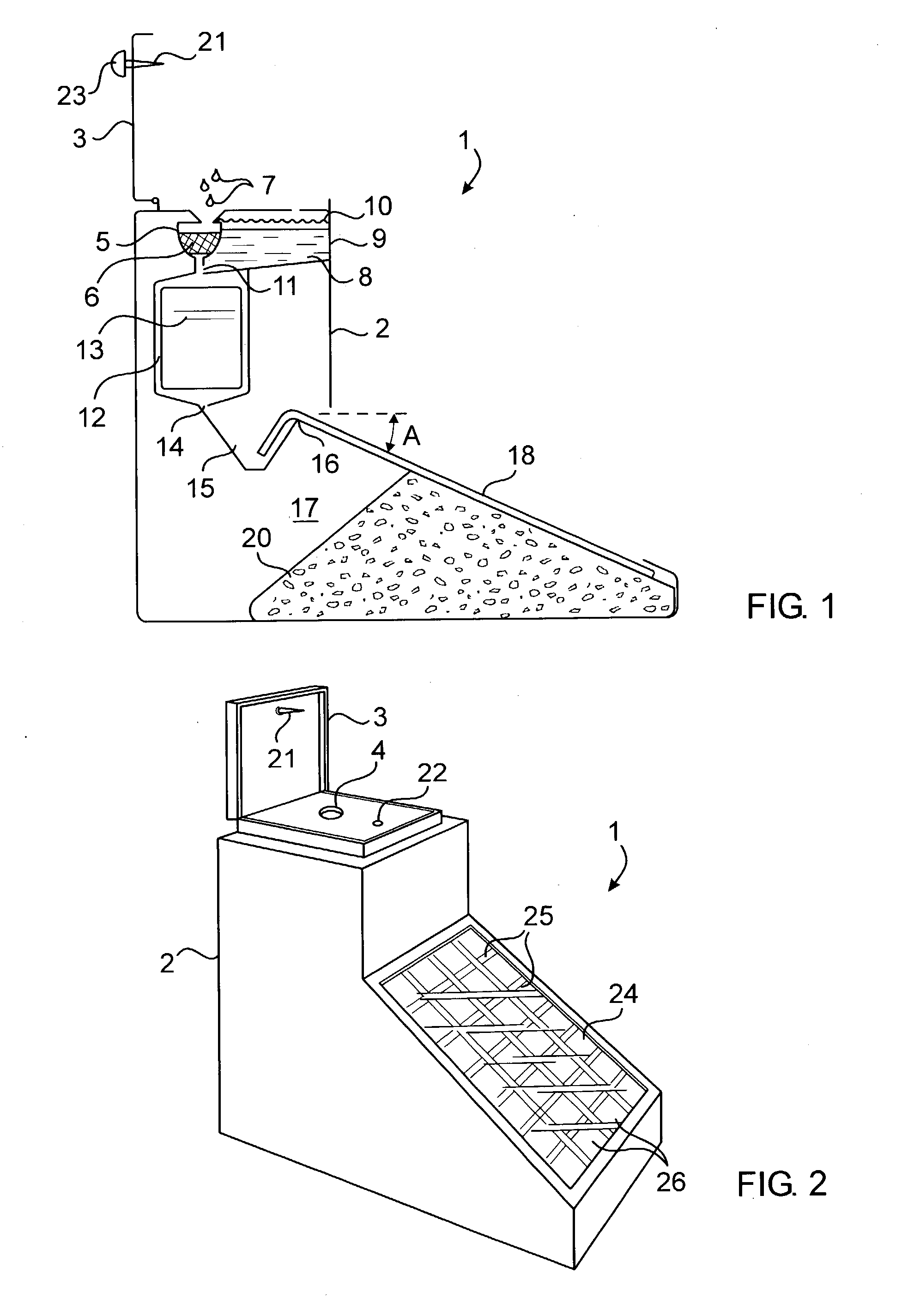
[0009] Referring now to the drawing, there is shown an immunoassay testing device 1 according to the invention. The device is preferably packaged in a molded plastic enclosure 2 topped by a sealing cap 3. In the upper region of the device, and immediately under a ceiling hole 4 is a sampling well 5. The internal wall of the well is funnel-shaped, and retains some filtration material 6. The geometry of that wall, whether in the form of a V or a U, has a portion of a relatively low pitch so that when a fluid specimen 7 such as whole blood, 7 or saliva runs along the wall, particles and adhesive matters are separated from the fluid component of the specimen. A supply of aqueous buffering solution 8 is held in a vessel 9 along side the sampling well. The vessel has a top opening hermetically sealed by a membrane 10, and a dispensing port 11 in a lower region leading to a first chamber 12 in a first analytical part of the device. The chamber is located immediately below the sampling well...


PUM

PropertyMeasurementUnit
pitch angleaaaaaaaaaa
atmospheric pressureaaaaaaaaaa
temperatureaaaaaaaaaa

Abstract

In a vertical flow immunoassay testing device, the fluid specimen is deposited in a sampling well whose inclined walls and filtration material separate mucus and other adhesive matters from the more fluid components. The mixing of the specimen with a buffer solution is triggered by the closure of the device's cap. The flow of the buffered specimen from a first chamber where it is exposed to a collodial gold conjugate to a second chamber holding a chromatographic test strip is temporarily interrupted by a holding reservoir. The specimen does not freely flow into the strip until the reservoir begins to overflow. The delay provides an incubation time for a better affinity binding of the specimen and regulates its flow through the strip.

Description

FIELD OF THE INVENTION [0001] This invention relates to analytical and confirmatory testing devices for analyzing body fluids using immunochromatography, and more particularly to apparatuses for concurrent performances of multiple antibody, or antigen detection on a common fluid test. BACKGROUND OF THE INVENTION [0002] Over past decades, the prior art has offered several types of rapid diagnostic testing techniques. First, were the latex particle agglutination tests, then the Flow Through tests leading to the current Lateral Flow Single Step test. To this day, the Western Blot Analytical Assay is the only one reliably used for the confirmatory detection of HIV infection in a clinical laboratory setting. Due to its multi-step manipulation and verification phases, this type of assay takes days, if not weeks. There is no practical confirmatory rapid diagnostic testing technique for use in a Point-of-Care setting, available in the market place today. [0003] The instant invention results...

Claims


Application Information

Patent Timeline
Patent Type & Authority Applications(United States)
IPC IPC(8): G01N33/53G01N33/558
CPCG01N2333/16G01N33/558
Inventor WANG, NAISHUZHOU, DAVID F.
Owner DNT SCI RES
Why Eureka
Try Eureka