
Refrigeration system

a refrigeration system and expansion valve technology, applied in refrigeration components, lighting and heating apparatus, heating types, etc., can solve the problems of other utilization side units degrading their refrigeration capacity or heating capacity, and achieve the effect of increasing the supply of refrigeration, enhancing the capacity, and small opening of the expansion valve (72)

Inactive Publication Date: 2009-11-19
DAIKIN IND LTD
View PDF2 Cites 12 Cited by
  • Summary
  • Abstract
  • Description
  • Claims
  • Application Information

AI Technical Summary

Benefits of technology

[0019]To cope with the above, in the fourth aspect of the present invention, the expansion valve (72) is forcibly opened if, in the second control operation, the expansion valve (72) has continuously been in the fully closed state for longer than a predetermined length of time. In this case, it is preferred that the degree of opening of the expansion valve (72) be as minimum as possible. With this arrangement, that is, by opening the expansion valve (72) in the above described manner, the elimination of “refrigerant's falling-asleep” within the heating heat exchanger (71) can be accomplished without fail, even when the degree of refrigerant subcooling (Pc−Th1) is detected having a small value due to the influence of the ambient temperature.
[0029]In addition, in the fourth aspect of the present invention, after the expansion valve (72) is opened to allow the flow of refrigerant through the heating heat exchanger (71), the degree of opening of the expansion valve (72) can further be controlled depending on the degree of refrigerant subcooling. As a result of such arrangement, the temperature of refrigerant flowing on the inflow side of the heating heat exchanger (71) or through the inside of the heating heat exchanger (71) is less subject to the influence of the ambient temperature of the heating heat exchanger (71), whereby it becomes possible to accurately detect the amount of refrigerant within the heating heat exchanger (71). Consequently, in accordance with the present invention, it is possible to properly control the degree of opening of the expansion valve (72) depending on the accumulated amount of refrigerant within the heating heat exchanger (71). This therefore ensures that the elimination of “refrigerant's falling-asleep” within the heating heat exchanger (71) is accomplished without fail and, in addition, it is possible to satisfactorily ensure the supply of refrigerant to the other utilization side units (13, 14).

Problems solved by technology

This gives rise to the problem that the other utilization side unit degrades in refrigeration capacity or heating capacity.

Method used


Image

  • Refrigeration system
  • Refrigeration system
  • Refrigeration system

Examples


Embodiment Construction

[0053]Hereinafter, with reference to the accompanying drawings, preferred embodiments of the present invention will be described in detail.

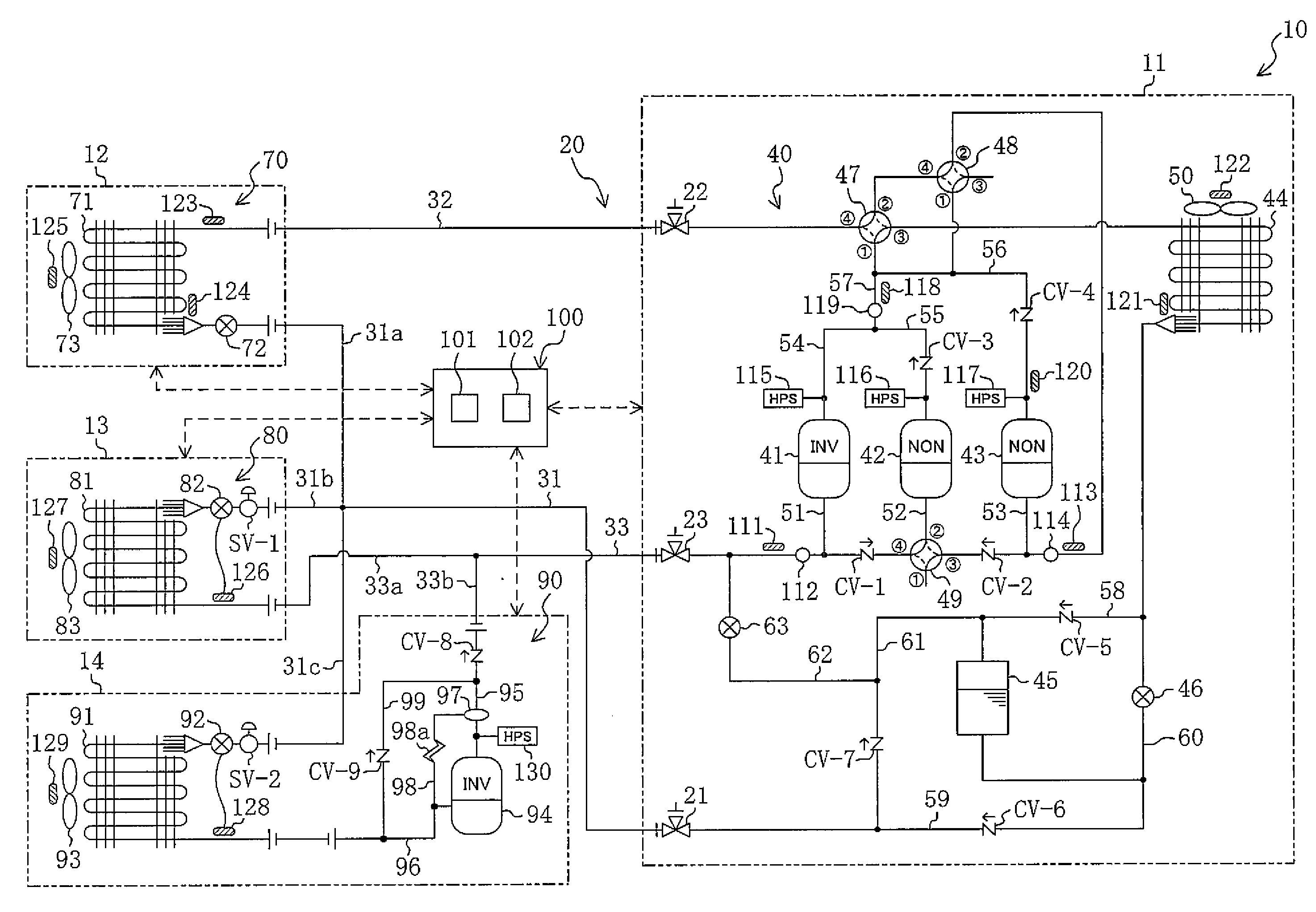
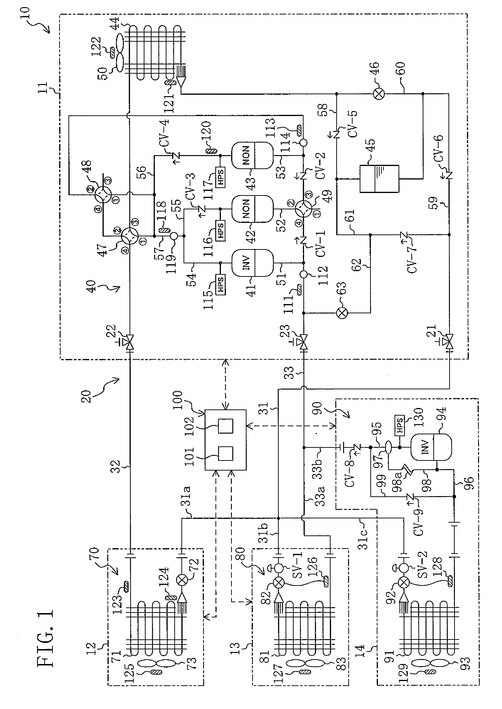
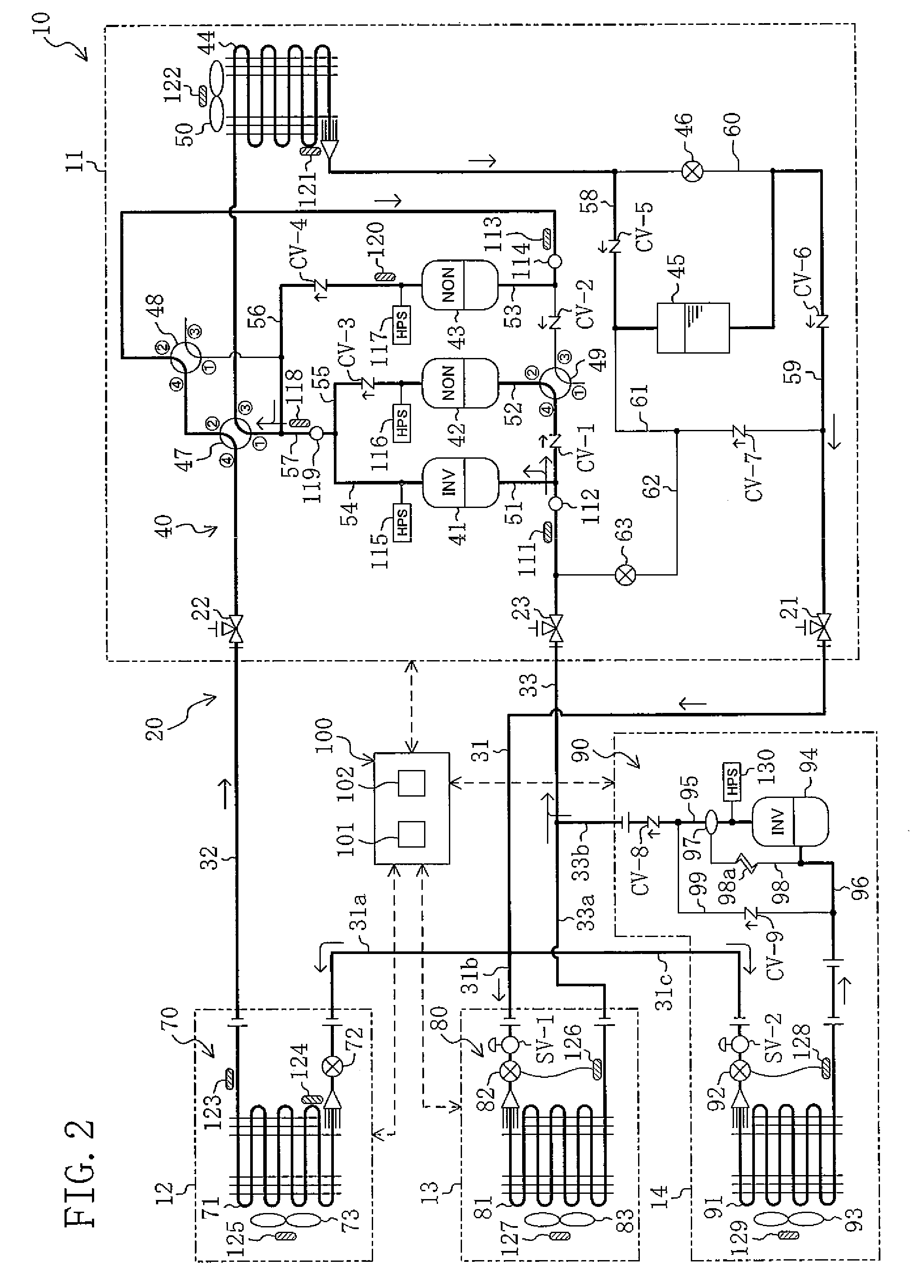
[0054]A refrigeration system (10) according to the present embodiment is of the type for the installation in a convenience store or other facility. The refrigeration system (10) provides, at the same time, refrigeration to a cold-storage compartment and a freeze-storage compartment and air conditioning to an indoor space.

[0055]As shown in FIG. 1, the refrigeration system (10) includes an outdoor unit (11), an air conditioning unit (12), a cold-storage showcase (13), and a freeze-storage showcase (14). The outdoor unit (11) is provided with an outdoor circuit (40) which constitutes a heat source side circuit. The air conditioning unit (12) is provided with an air conditioning circuit (70) which constitutes a first utilization side circuit. The cold-storage showcase (13) is provided with a cold-storage circuit (80) which constitutes a second utiliz...


PUM


Abstract

In a refrigerant circuit (20), an air conditioning unit (12), a cold-storage showcase (13), and a freeze-storage showcase (14) are connected in parallel to an outdoor unit (11). When placing an indoor heat exchanger (71) of the air conditioning unit (12) in the thermo-off state, a degree-of-opening control means (101) provides control so that an indoor expansion valve (72) is placed in the fully closed state. Thereafter, the degree-of-opening control means (101) detects the accumulated amount of refrigerant within the indoor heat exchanger (71) and then adjusts the degree of opening of the indoor expansion valve (72) depending on the refrigerant amount detected.

Description

TECHNICAL FIELD[0001]This invention generally relates to a refrigeration system having a plurality of utilization side units and more particularly to the prevention of the accumulation of refrigerant (“refrigerant's falling-asleep” in the industry jargon) in a heating heat exchanger placed out of operation.BACKGROUND ART[0002]In the past, various refrigeration systems that perform a refrigeration cycle by the circulation of refrigerant have widely been applied to air conditioning systems and other like systems. There is known, as such a type of refrigeration system, a so-called multi-type refrigeration system in which a plurality of utilization side units are connected in parallel to a heat source side unit.[0003]For example, JP-A-1996-159590 (hereinafter referred to as the patent document) shows a refrigeration system which includes a single heat source side unit having a compressor and a heat source side heat exchanger, and two utilization side units each having a utilization side...

Claims


Application Information

Patent Timeline
IPC IPC(8): F25B41/04F25B27/00
CPCF25B1/10F25B13/00F25B2313/0233F25B2313/02743F25B2313/0314F25B2313/0231F25B2400/19F25B2400/22F25B2600/2513F25B2700/04F25B2400/0751F24F3/06F24F5/001F24F11/63
Inventor TAKEGAMI, MASAAKINOMURA, KAZUYOSHIKONDO, AZUMAODA, YOSHINARITANIMOTO, KENJI
Owner DAIKIN IND LTD
Learn More