
Method and system for debugging through supervisory operating codes and self modifying codes

a technology of operating code and code, applied in the field of software and hardware development, can solve problems such as invalid marking of supervisory operation flags, and achieve the effect of convenient efficient utilization

Active Publication Date: 2007-02-27
MONTEREY RES LLC
View PDF11 Cites 84 Cited by
  • Summary
  • Abstract
  • Description
  • Claims
  • Application Information

AI Technical Summary

Benefits of technology

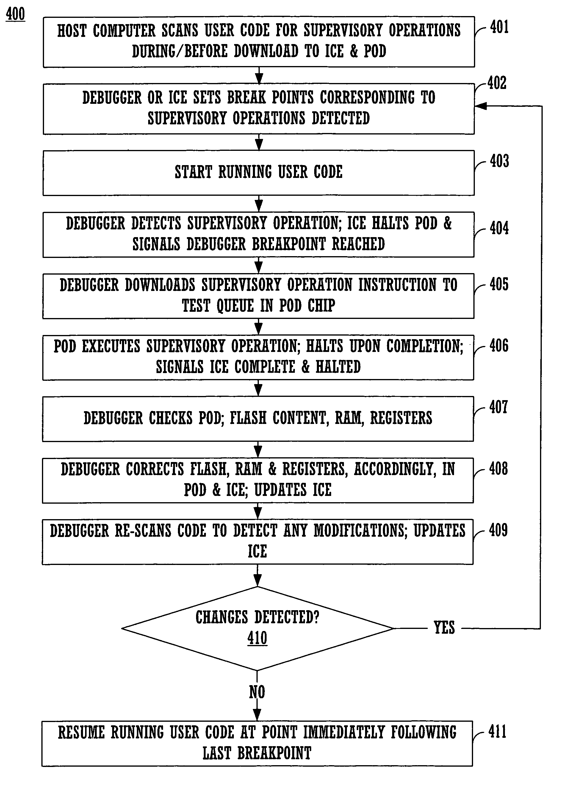
[0012]What is needed is a system and / or method for debugging that is easily open to efficient utilization in a distributed hardware environment. What is also needed is a system and / or method for debugging that does not require elaborate hardware to implement special functions not amenable to debugging per se and / or to allow code modification during debugging. Further, what is needed is a system and / or method for debugging wherein code modification implemented during a debugging session does not require restarting and / or repeating the session. Additionally, what is needed is a system and / or method for debugging that ensures lockstep execution during supervisory calls and flash updates. Embodiments of the present invention provide the above advantages.
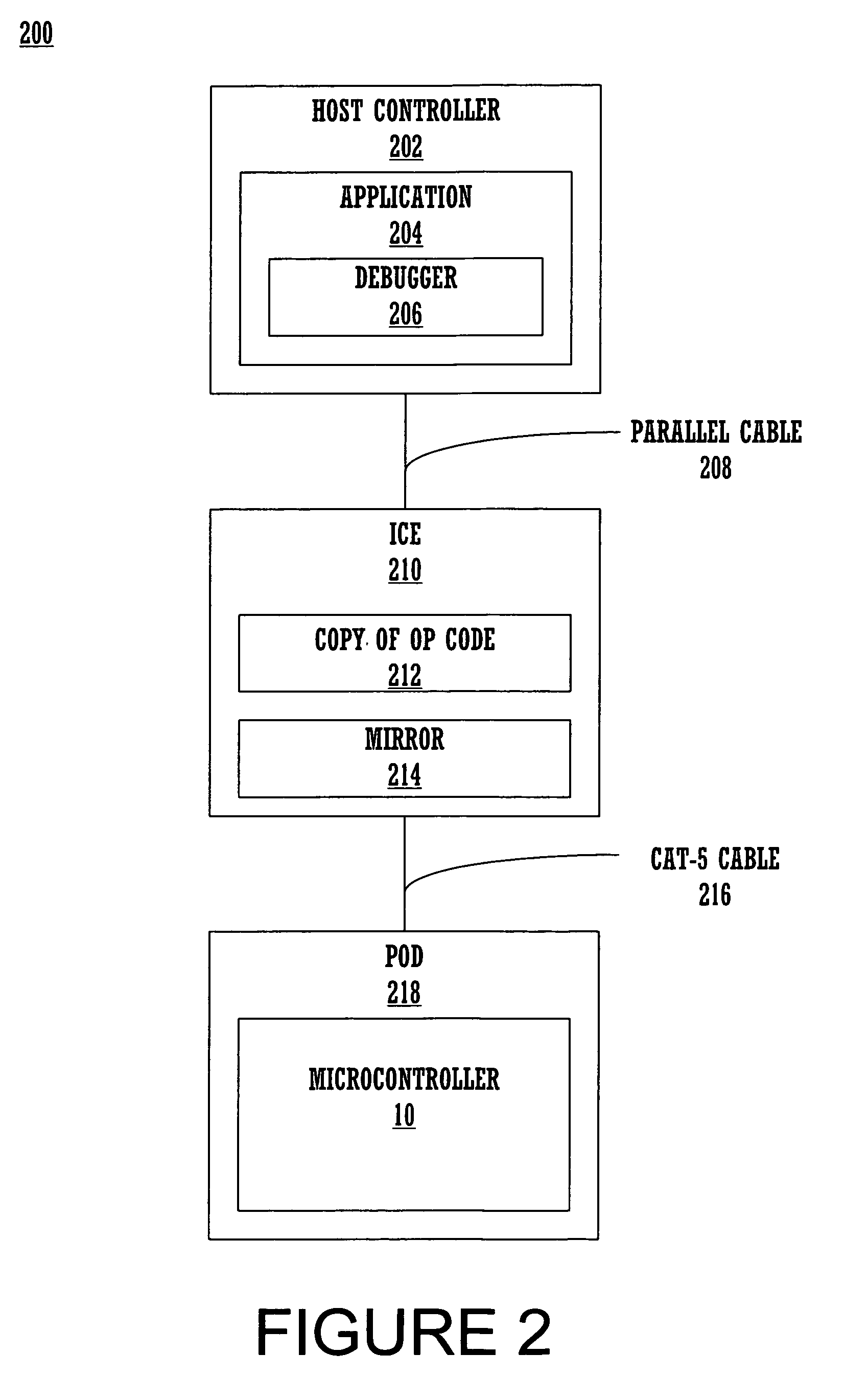
[0016]According to embodiments of the present invention, a device such as a microcontroller may be debugged in a distributed architectural scheme, where the device may operate at speeds much faster than the debugger program is run, with limited debugging resources physically incorporated into the device itself, and with relatively limited computational capacity, vis-à-vis the platform deploying the debugging software. The software demands on the debugger are not complicated by the debugging schemes of the present embodiments, and the ICE may also be kept relatively simple. Further, debugging schemes of the present embodiments are flexible and adaptable to a variety of different devices that must undergo debugging, yet the scheme remains effective, simple, and inexpensive.

Problems solved by technology

Further, the old supervisory operation flags may be marked as invalid, and a user alert may be promulgated.

Method used


Image

  • Method and system for debugging through supervisory operating codes and self modifying codes
  • Method and system for debugging through supervisory operating codes and self modifying codes
  • Method and system for debugging through supervisory operating codes and self modifying codes

Examples


Embodiment Construction

[0025]In the following detailed description of the present invention, numerous specific details are set forth in order to provide a thorough understanding of the present invention. However, it will be recognized by one skilled in the art that the present invention may be practiced without these specific details or with equivalents thereof. In other instances, well known methods, procedures, components, and circuits have not been described in detail as not to unnecessarily obscure aspects of the present invention.

[0026]Notation and Nomenclature

[0027]Some portions of the detailed descriptions, which follow, are presented in terms of procedures, steps, logic blocks, processing, and other symbolic representations of operations on data bits that can be performed by computer systems. These descriptions and representations are used by those skilled in the data processing arts to most effectively convey the substance of their work to others skilled in the art. A procedure, computer executed...


PUM


Abstract

Embodiments of the present invention effectuate a method and system for debugging a device such as a microcontroller in a distributed architectural scheme, where the device may operate at speeds much faster than the debugger program is run, with limited debugging resources physically incorporated into the device itself, and with relatively limited computational capacity, vis-à-vis the platform deploying the debugging software. The embodiments place relatively modest, uncomplicated demands on the debugger software, and the ICE may also be relatively simple. Further, debugging methods and systems according to these embodiments are flexible and adaptable to a variety of different devices that must undergo debugging, yet remain effective, simple, and inexpensive.

Description

TECHNICAL FIELD[0001]The present invention relates to the field of software and hardware development. Specifically, the present invention relates to development tools, especially useful for debugging microcontroller programs.BACKGROUND ART[0002]Debugging software (e.g., a debugger) effectuates correction of problems in software by finding errors in program logic, and in hardware by finding errors in circuitry. Debuggers can be used to stop programs at certain breakpoints and display various programming elements. This allows programmers to step through program source code statements individually and sequentially, while corresponding machine instructions are being executed and observed, and correct and / or modify the code as necessary.[0003]Conventional debuggers operate to stop programs at the breakpoints by implementing system management interrupts (SMI) or similar functions. However, SMIs and similar approaches to halting program execution at breakpoints are effective in situations ...

Claims


Application Information

Patent Timeline
Patent Type & Authority Patents(United States)
IPC IPC(8): G06F9/44G06F11/00
CPCG06F11/3664G06F11/3636
Inventor ROE, STEVEPLEIS, MATTNEMECEK, CRAIG
Owner MONTEREY RES LLC
Learn More