Seal and Fixation Assembly for a Rotating Cylindrical Magnetron Electrode

Active Publication Date: 2012-06-14
ANGSTROM SCI
View PDF1 Cites 0 Cited by
  • Summary
  • Abstract
  • Description
  • Claims
  • Application Information

AI Technical Summary

Benefits of technology

[0008]According to an embodiment of the present invention, a seal and fixation assembly for a rotating cylindrical magnetron electrode is provided. The seal and fixation assembly includes a cylindrical target having an exterior and a hollow interior defining an inside surface of the cylindrical target. The inside surface includes an internal shoulder proximate to an end of the cylindrical target that forms a stop within the hollow interior of the target. A target retaining ring is disposed about the exterior of the cylindrical target. The target retaining ring has an external tapered surface. A seal plate is disposed within the hollow interior of the cylindrical target. The seal plate engages the stop and the inside surface of the cylindrical target. An end cap is disposed on the end of the cylindrical target. The end cap includes an external portion engaging the exterior of the cylindrical target and an internal portion engaging the inside surface of

Problems solved by technology

However, the external sealing surfaces tend to scratch during ass

Method used


Image

  • Seal and Fixation Assembly for a Rotating Cylindrical Magnetron Electrode
  • Seal and Fixation Assembly for a Rotating Cylindrical Magnetron Electrode
  • Seal and Fixation Assembly for a Rotating Cylindrical Magnetron Electrode

Examples


Example

[0019]For purposes of the description hereinafter, spatial orientation terms, if used, shall relate to the referenced embodiment as it is oriented in the accompanying drawing figures or otherwise described in the following detailed description. However, it is to be understood that the embodiments described hereinafter can assume many alternative variations and embodiments. It is also to be understood that the specific devices illustrated in the accompanying drawing figures and described herein are simply exemplary and should not be considered as limiting.

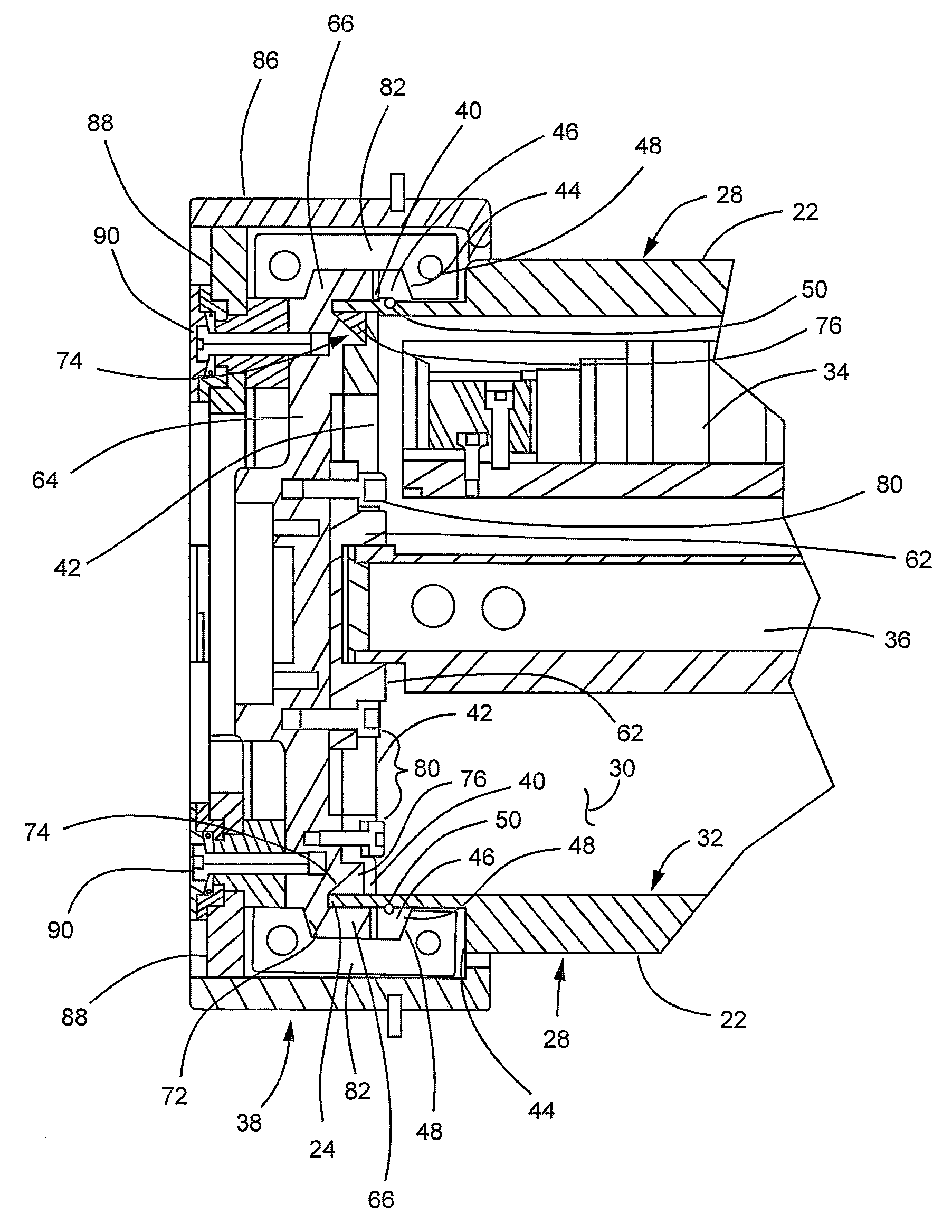
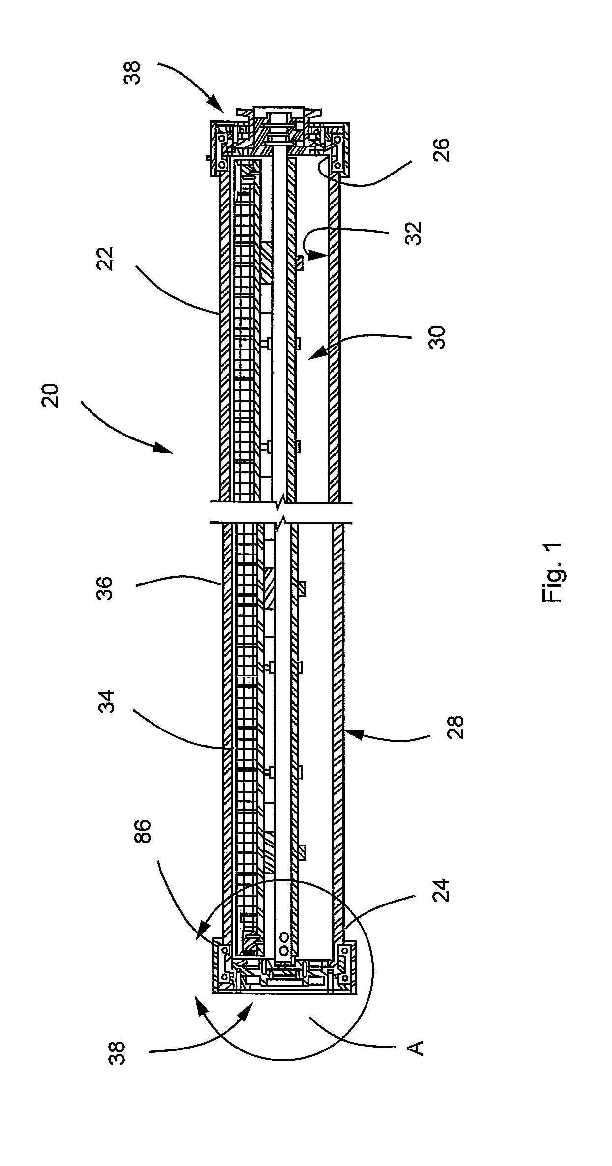
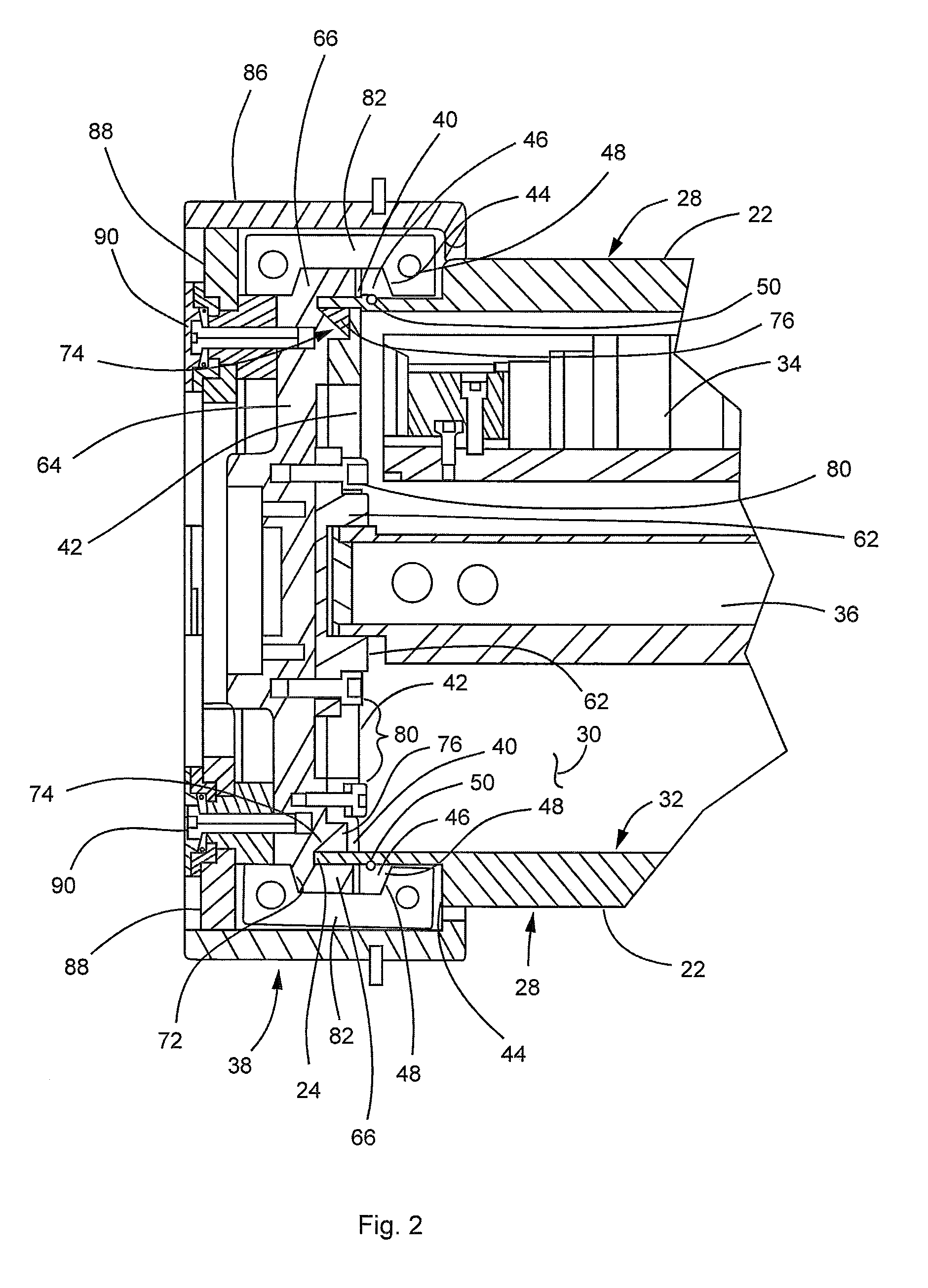
[0020]With reference to FIG. 1, a rotating cylindrical magnetron electrode 20, according to an embodiment of the present invention, is shown. In the following discussion, the electrode 20 is designed for use in a cylindrical magnetron of the type disclosed in United States Patent Application Publication Nos. 2008 / 0012460 entitled “Magnetron for Cylindrical Targets” (hereinafter also referred to “USPP 2008 / 0012460”) and 2009 / 0260983 ...


PUM


Abstract

A seal and fixation assembly includes a cylindrical target having an inside surface with a shoulder that forms a stop within the target. A target retaining ring is disposed about the target. A seal plate is disposed within the target and engages the stop and the inside surface of the target. An end cap is disposed on the end of the target and includes a portion with a beveled surface within the target. A sealing element is disposed between the inside surface of the target, the seal plate, and the beveled surface of the end cap. A clamp is disposed over the end cap and the target retaining ring. Engagement of the end cap and the target retaining ring with the clamp causes the end cap to move within the target toward the stop to compress the sealing element between the target, the seal plate, and the beveled surface.

Description

CROSS REFERENCE TO RELATED APPLICATIONS[0001]This application claims the benefit of U.S. Provisional Patent Application No. 61 / 419,678, filed Dec. 3, 2010, and titled “Seal and Fixation Assembly for a Rotating Cylindrical Magnetron Electrode”. This application is related to the subject matter disclosed in U.S. Provisional Patent Application No. 61 / 298,613, filed Jan. 27, 2010, and titled “Seal and Fixation Assembly for a Rotating Cylindrical Magnetron Electrode”. The disclosures of Application No. 61 / 419,678 and of Application No. 61 / 298,613 are incorporated herein by reference in their entirety.BACKGROUND OF THE INVENTION[0002]1. Field of the Invention[0003]The present invention relates to a seal and fixation assembly for closing and sealing the ends of a cylindrical electrode target of a rotating cylindrical magnetron electrode. More particularly, the present invention relates to a seal and fixation assembly that utilizes an internal sealing element disposed between three sealing ...

Claims


Application Information

Patent Timeline
IPC IPC(8): H01J25/50F16J15/16
CPCF16J15/062Y10T403/32975
Inventor NEWCOMB, RICHARD
Owner ANGSTROM SCI
Why Eureka
Try Eureka