Data synchronization among file storages using stub files

a file storage and data synchronization technology, applied in the field of storage systems, to achieve the effect of non-disruptive file storage system transition

Active Publication Date: 2012-06-14
HITACHI LTD
View PDF6 Cites 47 Cited by
  • Summary
  • Abstract
  • Description
  • Claims
  • Application Information

AI Technical Summary

Benefits of technology

[0003]Exemplary embodiments of the invention provide methods and apparatus to enable seamless transition and data synchronization among file storage systems. Specific embodiments are directed to file storage system apparatus supporting file-level HSM (Hierarchical Storage Management), and are designed to enable non-disruptive file storage sys

Problems solved by technology

The second situation is that the new file storage system has mostly the same files but some of the files are different because the new

Method used


Image

  • Data synchronization among file storages using stub files
  • Data synchronization among file storages using stub files
  • Data synchronization among file storages using stub files

Examples


first embodiment

[0032]A. System Configuration

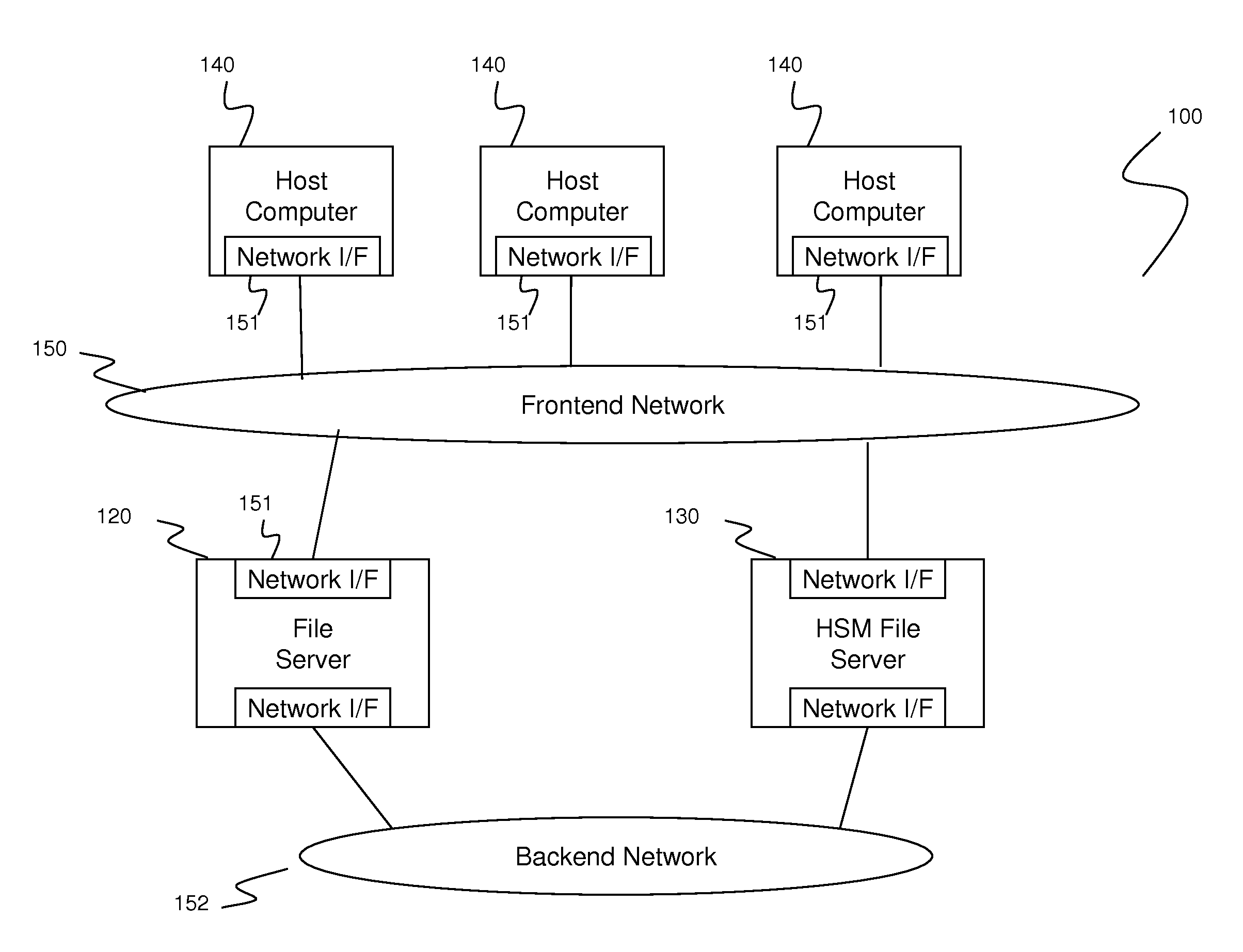
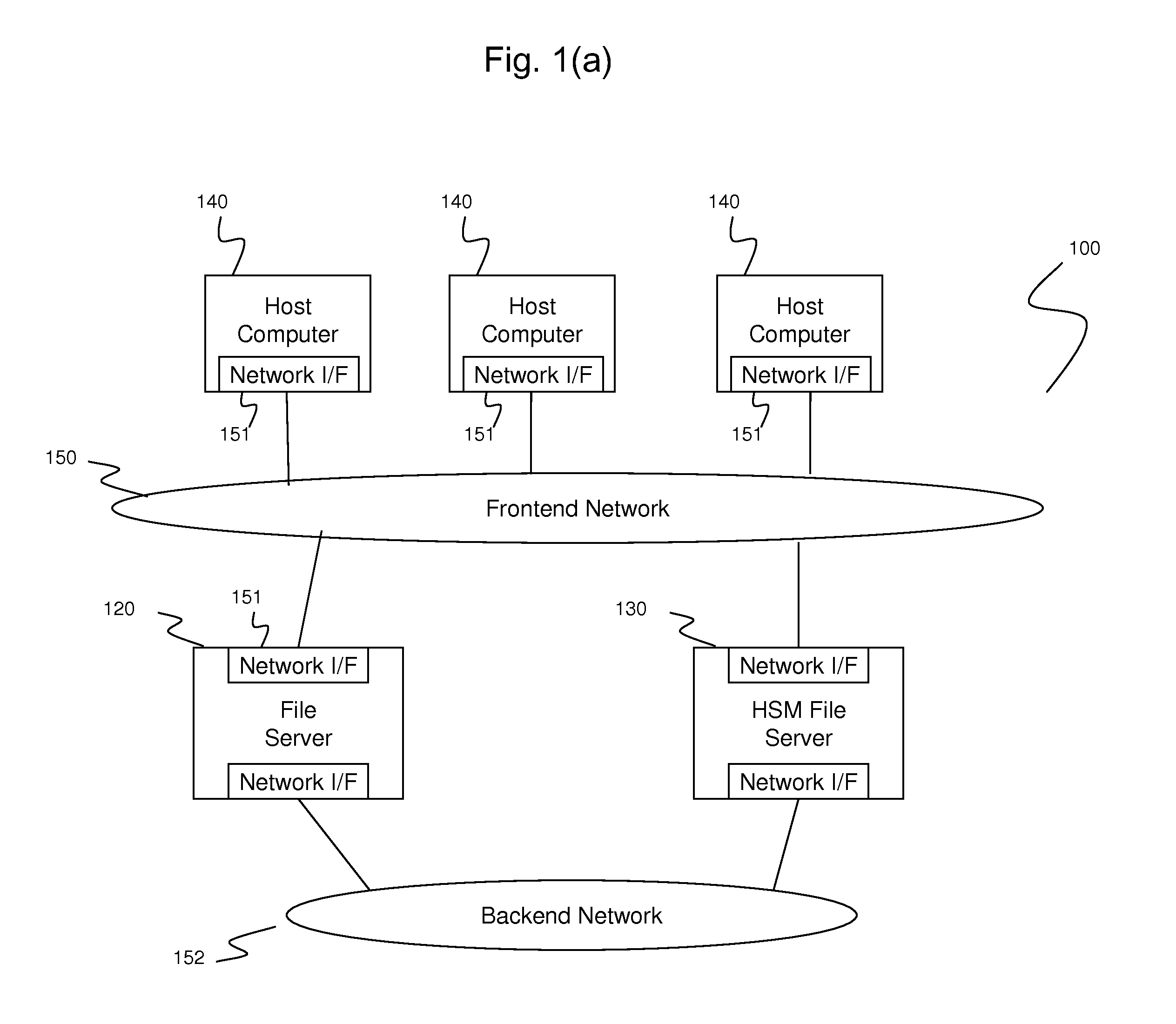
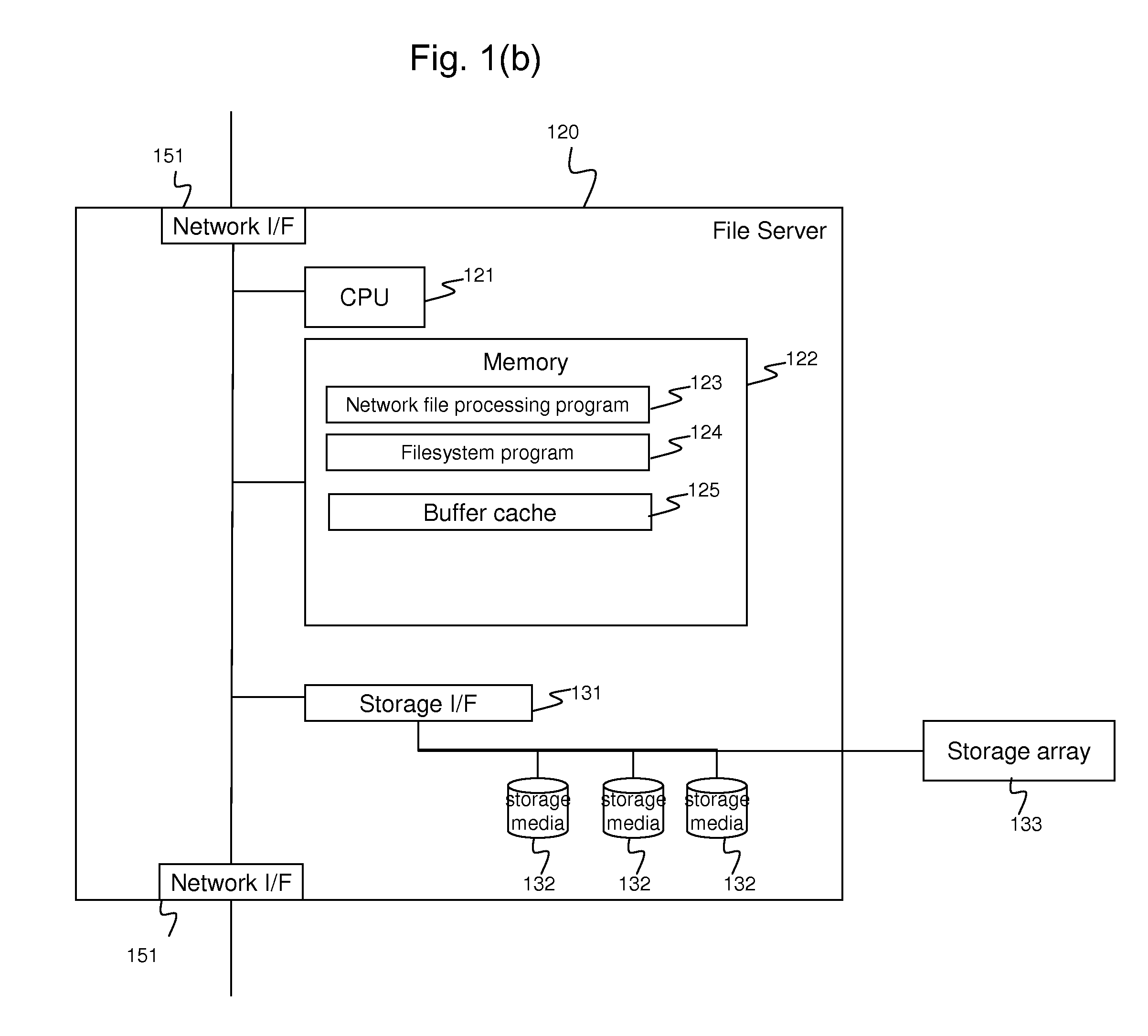
[0033]FIGS. 1(a), (b), (c), and (d) show an example of the information system overview 100 in which the method and apparatus of the invention may be applied. The information system 100 includes a file server 120, a HSM file server 130, a frontend network 150, a backend network 152, and one or more host computers 140.

[0034]The file server 120 is the old file server from which users of the information system 100 want to transit to the newer file server 130. As seen in FIG. 1(b), the file server 120 includes a CPU 121, a memory 122, a storage interface 131, and network interfaces 151. The file server 120 may also have storage media 132. The CPU 121 controls the devices in the file server 120 using the programs in the memory 122. The memory 122 has programs and cache. The network interfaces 151 are used to communicate with the host computers 140 via the frontend network 150 and other file servers including the HSM file server 130 via the backend network 152....

second embodiment

[0054]Data synchronization via the backend network 152 takes much time, especially if the file storages 120 and 130 are distant, because generally the bandwidth of the network becomes less as the distance becomes longer. There is another synchronization method that the users can use to add storage media 132 into the file server 120, copy data among the storage media 132 internally, carry these media physically, install the media into the new HSM file server 130, and copy data among the media 132 in the new server 130. This method is effective, especially when the bandwidth of the backend network 152 is much lower than that of the internal copy among the storage media 132.

[0055]However, a problem remains that the physical transfer and installation of the storage media 132 take much time, even if these processes are much faster than the completion of synchronization via the backend network 152. The users can continue their business during the synchronization. When data synchronization...

third embodiment

[0063]FIGS. 8(a), (b), and (c) show an example of the information system overview 800 in which the method of this invention is not applied. As seen in FIG. 8(a), the local information system 850a comprises the existing file server 810 which is the same as the file server 120 of FIG. 1(a), host computers 140, and frontend network 150. The information system overview 800a is made of a single local information system 850a. As a result, a disaster such as earthquake or power blackout stops the local information system 850a and causes a loss of data stored in the existing file server 810.

[0064]The information system overview 800b includes a remote file server 820, as seen in FIG. 8(b). The host computers 140 in the local information system 850b issue file I / O requests to the remote file server 820. The remote file server 820 is the same as the file server 120 but located distantly from the local information system 850b so that the remote file server 820 remains unaffected by disaster and...


PUM


Abstract

A method switches file server from old file server to new file server which are coupled via a backend network and provides data synchronization. The old file server and new file server are coupled with one or more host computers via a frontend network to direct input/output (I/O) requests from the one or more host computers. The method comprises creating stub files in the new file server, the stub files including stub information indicating location of data in the old file server; switching I/O requests directed to old file server to I/O requests directed to the new file server; checking whether the new file server has any stub files; and, if the new file server has one or more stub files, recalling data corresponding to the one or more stub files from the old file server according to the stub information to replace the one or more stub files.

Description

BACKGROUND OF THE INVENTION[0001]The present invention relates generally to storage systems and, more particularly, to methods and apparatus for transition among file storage systems.[0002]When computer system users replace old storage systems with new ones or construct DR (Disaster Recovery) for BS (Business Continuity), data synchronization among storage systems is needed to take over the workload. Recent recording media have much higher capacity than before. Thus, it takes much more time, sometimes longer than a week, to synchronize data between storage systems. Users do not want to stop their business for such a long time to wait for the synchronization to complete; they would like to continue their business even during synchronization.BRIEF SUMMARY OF THE INVENTION[0003]Exemplary embodiments of the invention provide methods and apparatus to enable seamless transition and data synchronization among file storage systems. Specific embodiments are directed to file storage system ap...

Claims


Application Information

Patent Timeline
IPC IPC(8): G06F17/00G06F15/173
CPCG06F17/30176G06F17/30079G06F17/30221G06F17/30174G06F17/30153G06F3/0607G06F3/0647G06F3/067G06F16/1787G06F16/119G06F16/178G06F16/185G06F16/1744
Inventor MATSUZAWA, KEIICHI
Owner HITACHI LTD
Why Eureka
Try Eureka