Visual Display System

a technology of visual display and display screen, which is applied in the field of visual display system, can solve the problem that none of these disclosures addresses the problem of large screen us

Inactive Publication Date: 2012-06-21
THE PROCTER & GAMBLE COMPANY
View PDF8 Cites 1 Cited by
  • Summary
  • Abstract
  • Description
  • Claims
  • Application Information

AI Technical Summary

Benefits of technology

[0009]According to one embodiment of the invention, there is provided a visual display system that allows meeting attendees to face each other in a typical conference room manner. Visual information will be displayed above the heads of the meeting attendees located opposite them at the table. This display system produces a comfortable meeting atmosphere where attendees can sit face-to-face, glancing up slightly to view a large amount of displayed information. The visual display system includes at least two visual displays, where each visual display is produced using more than one image displaying device, and where at least two of the visual displays are oriented so that they are directed towards each other. The system further includes a CPU, and the lower edge of each of visual displays is elevated at least about 48 inches from the floor. In one embodiment of the invention, the image displaying devices are selected from the group consisting of projectors operating in combination with a screen or wall, LCD screens, LED screens, plasma screens and CRT screens.

Problems solved by technology

However, none of these disclosures address the issue of using large screens in a meeting / conference room environment, where the meeting participants typically face each other around a table.

Method used


Image

  • Visual Display System
  • Visual Display System
  • Visual Display System

Examples


Embodiment Construction

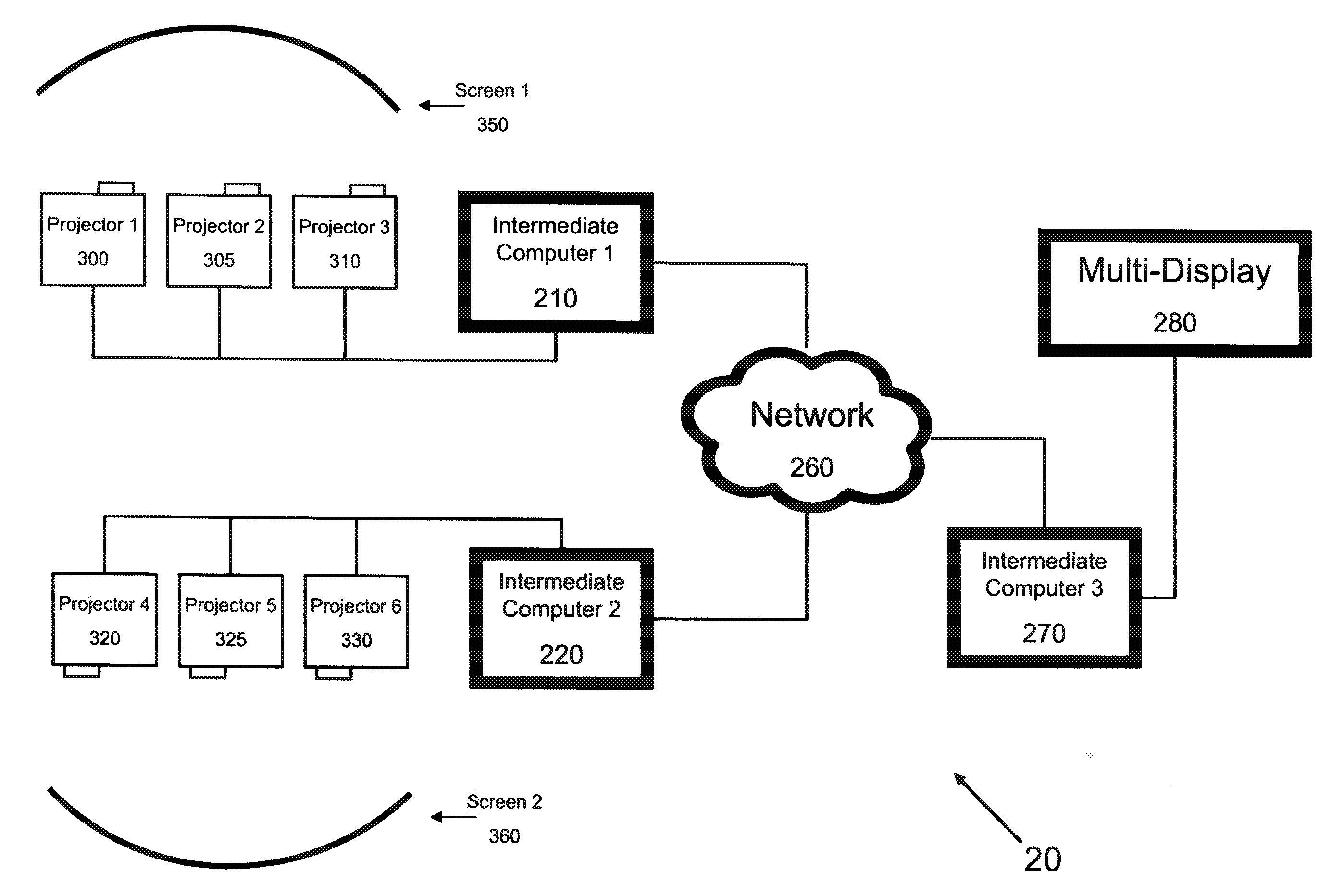
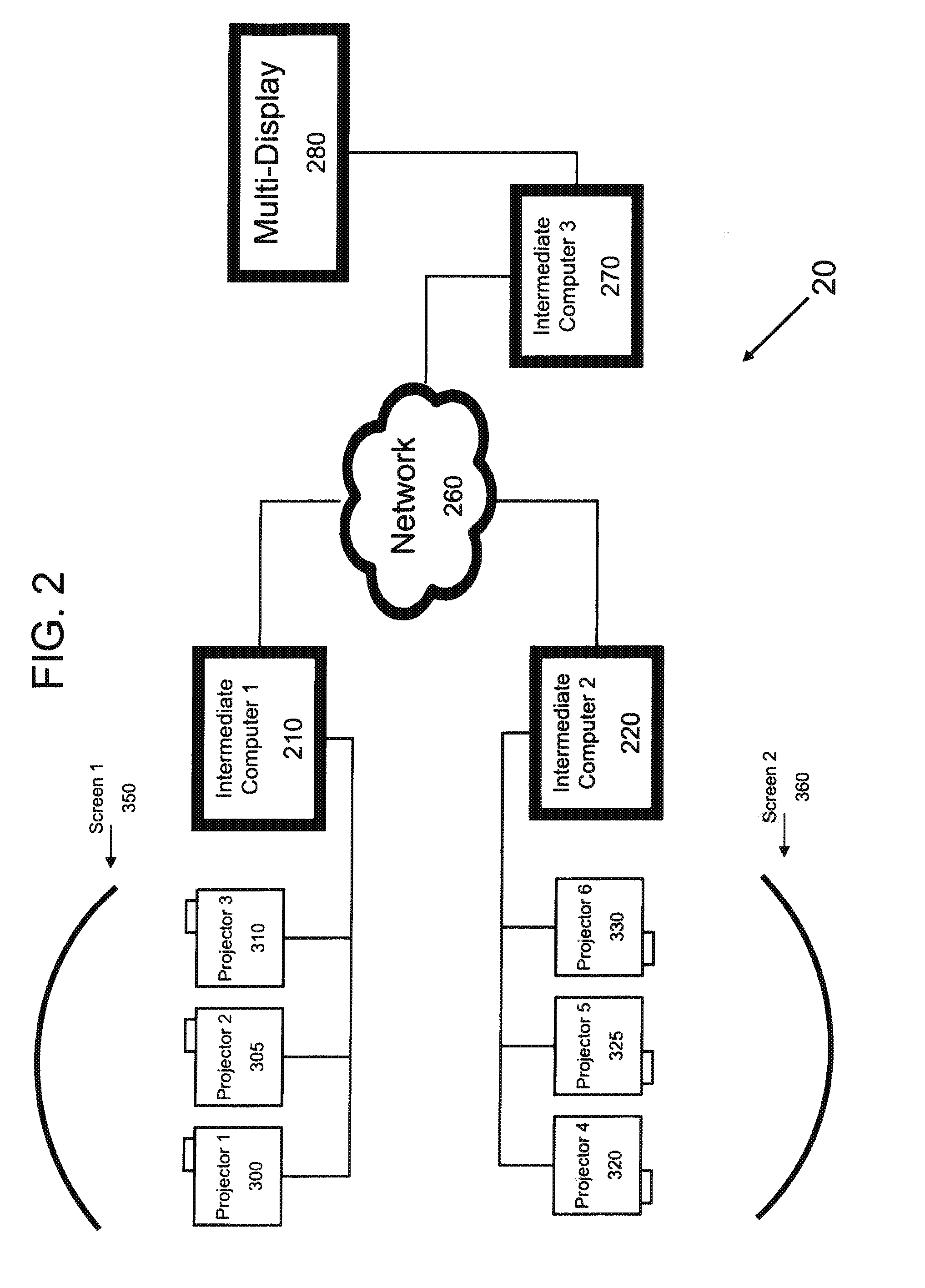
[0015]The system of the present invention is suitable for displaying large amounts of visual information simultaneously at multiple locations in a room. For purposes of illustrating the present invention in detail, but without intending to limit the scope of the invention, the invention will be described as a system for displaying visual information using multiple displays in multiple areas within a room.

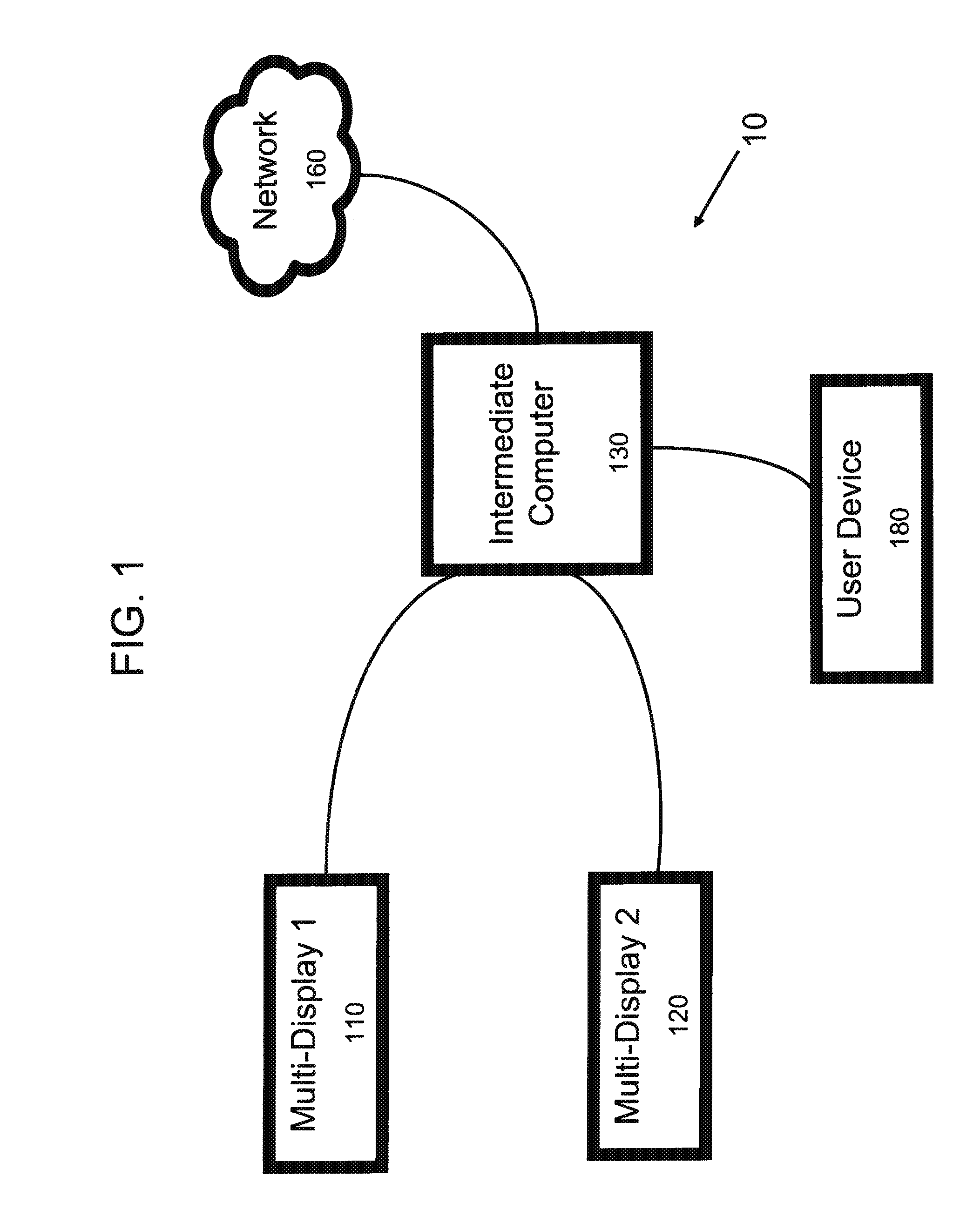
[0016]Referring to FIG. 1, a system 10 is represented comprising at least two Multi-Displays 110 and 120, which display the same visual image being provided by an Intermediate Computer 130. The Intermediate Computer 130 is connected to a User Device 180. The Intermediate Computer 130 is also connected to a Network 160 to allow communication with computers in other locations.

[0017]In one aspect of the invention, the Multi-Displays 110 and 120 may comprise multiple projectors operating in combination with a screen or wall, multiple LCD screens, multiple LED screens, multiple plasma sc...


PUM


Abstract

A visual display system and method for displaying information are disclosed. The visual display system includes at least two visual displays, where each visual display is produced using more than one image displaying device, and where at least two of the visual displays are oriented so that they are directed towards each other. The system further includes a CPU, and the lower edge of each of visual displays is elevated at least about 48 inches from the floor. In one embodiment of the invention, the image displaying devices are selected from the group consisting of projectors operating in combination with a screen or wall, LCD screens, LED screens, plasma screens and CRT screens.

Description

CROSS REFERENCE TO RELATED APPLICATIONS[0001]This application claims the benefit of U.S. Provisional Application No. 61 / 371,384, filed Aug. 6, 2010.FIELD OF THE INVENTION[0002]The present invention relates to a system for displaying large amounts of visual information using multiple displays in multiple areas within a room.BACKGROUND OF THE INVENTION[0003]It is generally known to produce a single visual image using multiple visual displays. The images from multiple projectors have been combined to produce a large, continuous image. Prior patents and other disclosures have disclosed methods for blending multiple images, with particular focus on the smooth transition of the image as it crossed between images from different projectors.[0004]U.S. Pat. No. 7,367,681 discloses a method and device for combing images from at least two light projectors. The patent focuses on a method for obtaining predictable image characteristics in the transition zone between overlapping images.[0005]U.S. ...

Claims


Application Information

Patent Timeline
Patent Type & Authority Applications(United States)
IPC IPC(8): G09G5/00
CPCH04N1/00129
Inventor GROVER, BRETT LORINGOTHICK, WILLIAM HENRYDUERSCH, BRENT JEREMY
Owner THE PROCTER & GAMBLE COMPANY
Why Eureka
Try Eureka