Progressing Cavity Pump/Motor

a technology of pumping cavity and motor, which is applied in the direction of machines/engines, mechanical equipment, liquid fuel engines, etc., can solve the problems of limited operating temperature and pressure of progressing cavity downhole pumps and motors, and achieve the effect of improving the operating temperature and pressure of the temperature and pressure of the progressing cavity downhole pump and motor

Active Publication Date: 2012-06-21
ROBBINS & MYERS ENERGY SYST
View PDF4 Cites 14 Cited by
  • Summary
  • Abstract
  • Description
  • Claims
  • Application Information

AI Technical Summary

Problems solved by technology

Operating temperatures and pressures for progressing cavity downhole pumps and motors has been generally

Method used


Image

  • Progressing Cavity Pump/Motor
  • Progressing Cavity Pump/Motor
  • Progressing Cavity Pump/Motor

Examples


Embodiment Construction

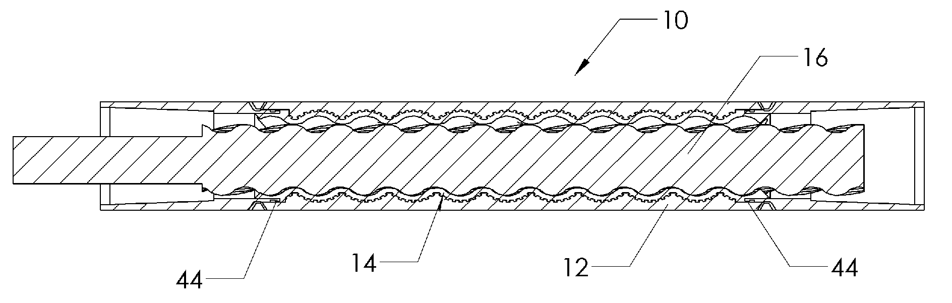
[0017]FIG. 8 depicts a progressing cavity pump / motor 10 having an outer rigid stator housing 12, a polymeric layer 14 molded within the housing 12 and a rotor 16 which rotates relative to the housing and the polymeric layer. In a downhole pump application, rotor 16 is conventionally rotated by a rod string extending to the surface, and frequently pumps fluid to the surface. In a downhole motor application, fluid pressure from the surface to the motor rotates the rotor 16, which in turn may rotate a drill bit. For a 1:2 geometry with 1 lobe on the rotor and two lobes on the stator, the exterior of the stator housing 12 may be cylindrical, or the stator housing may have a profiled or spiraling exterior configuration, with an exterior stator surface matching the interior stator profile. While a polymeric layer may have a varying thickness, the benefits disclosed herein are particularly well suited for a polymeric layer with a substantially even rubber thickness (ERT). Conventional desi...


PUM

PropertyMeasurementUnit
Thicknessaaaaaaaaaa
Widthaaaaaaaaaa
Perimeteraaaaaaaaaa

Abstract

A progressing cavity pump/motor (10) includes a stator housing (12), a polymeric layer (14), and a rotor (16). A plurality of axially extending grooves (24) are formed in the interior surface of the stator housing for receiving polymeric material therein. At least one seal gland (46) adjacent an end of the polymeric layer maintains sealing between the stator housing and the polymeric layer.

Description

FIELD OF THE INVENTION[0001]The present invention relates to progressing cavity pumps and motors, and more particularly relates to improvements in downhole progressing cavity pumps or motors which facilitate reliable operation at relatively high temperatures and / or pressures.BACKGROUND OF THE INVENTION[0002]Operating temperatures and pressures for progressing cavity downhole pumps and motors has been generally considered to be limited by the adhesive used to bond the polymeric sleeve to the stator tube or housing. A seal gland of the type disclosed in U.S. Pat. No. 7,407,372 in a downhole pump or motor operates well in steam and high sand content wells where conventional bonding of the polymeric layer to the stator has failed.[0003]Axial grooves in the inside wall of a cylindrical stator tube have been proposed to prevent rotation of the polymeric sleeve due to torque. These grooves are large relative to the stator tube, and were often a quarter or more of the tube width. Other manu...

Claims


Application Information

Patent Timeline
IPC IPC(8): F01C1/16B23P15/00
CPCF04C2/1075Y10T29/49242F01C1/22F04C13/008
Inventor GUIDRY, JR., MICHAEL J.
Owner ROBBINS & MYERS ENERGY SYST
Why Eureka
Try Eureka