Driving Microneedle Arrays into Skin and Delivering RF Energy

Inactive Publication Date: 2012-06-21
CANDELA CORP
View PDF21 Cites 149 Cited by
  • Summary
  • Abstract
  • Description
  • Claims
  • Application Information

AI Technical Summary

Benefits of technology

[0005]An array of needles can be held retracted in a protective cartridge. The array of needles can be deployed by an electric solenoid or pneumatic driver, which is used to drive the needle array into skin at a desired velocity. The array can be an array of microneedles. The needles can

Problems solved by technology

However, this patent fails to address how to overcome the difficulties of preventing skin from being pushed out of the way by the microneedle array, particularly when the spacings between the needles are small (bed-of-nails effect).
However, this patent fails to teach the use of vacuum to press skin against a plate, and combining pressure and reduced temperature to improve patient comfort by reducing pain.
It also

Method used


Image

  • Driving Microneedle Arrays into Skin and Delivering RF Energy
  • Driving Microneedle Arrays into Skin and Delivering RF Energy
  • Driving Microneedle Arrays into Skin and Delivering RF Energy

Examples


Embodiment Construction

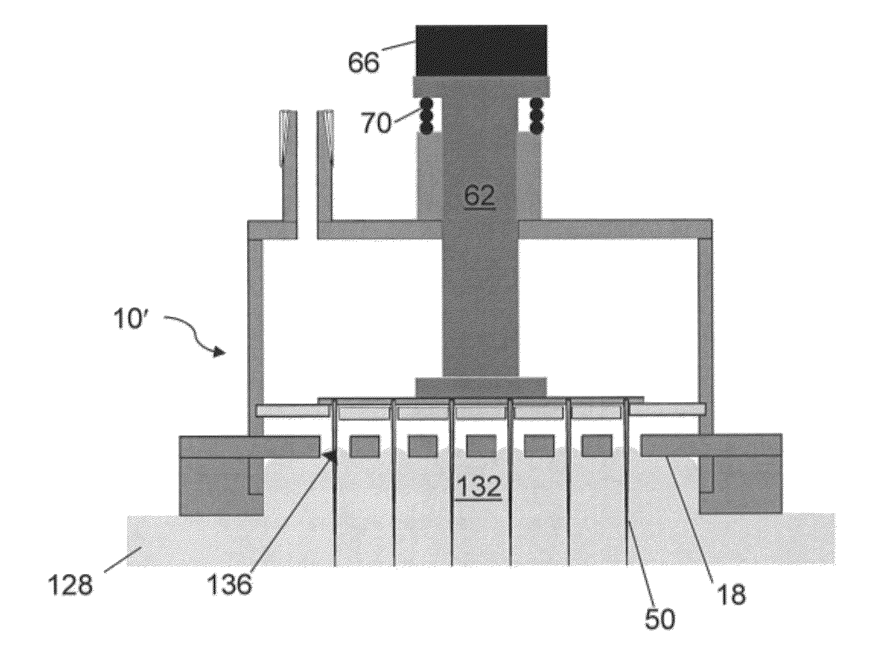
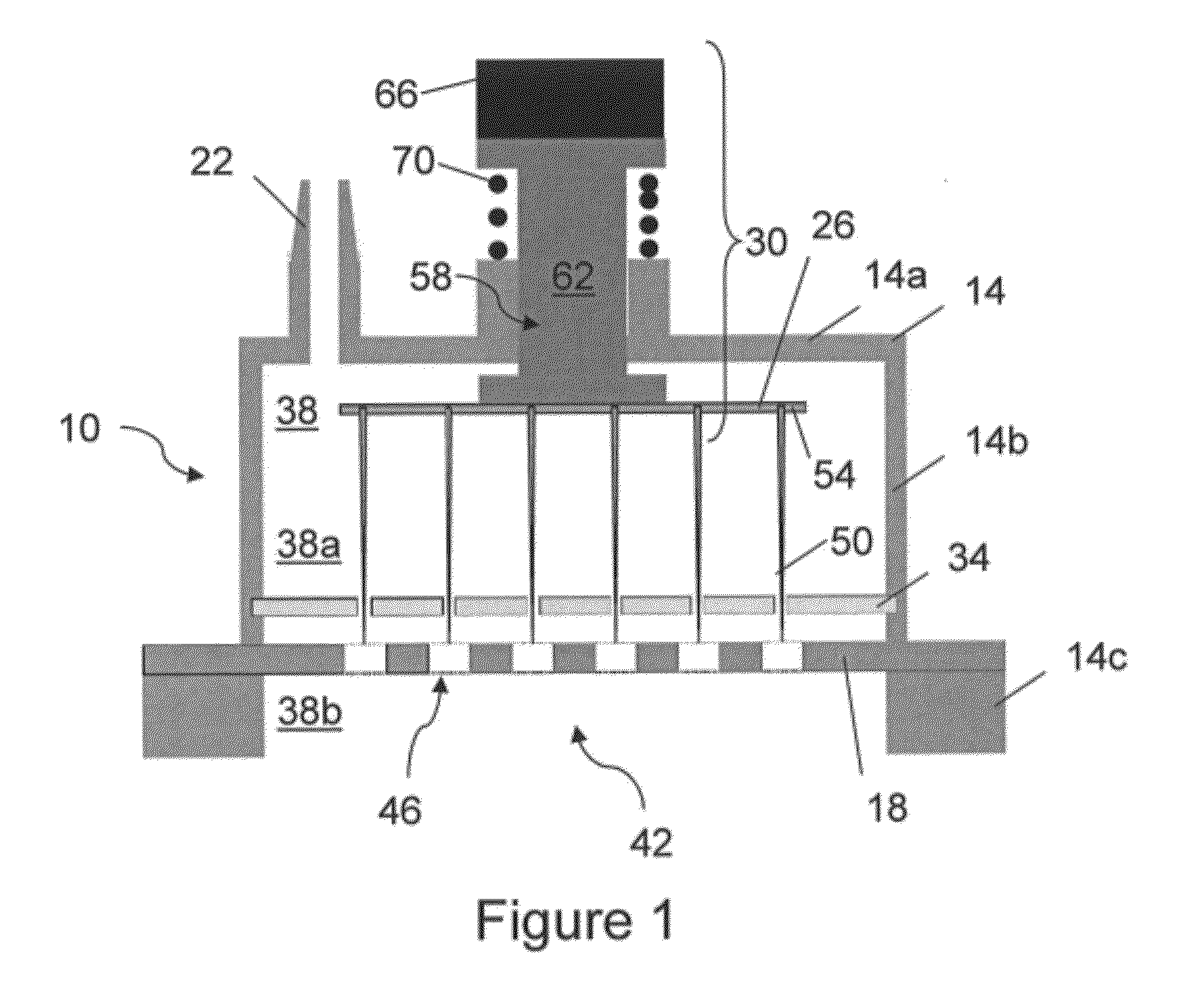
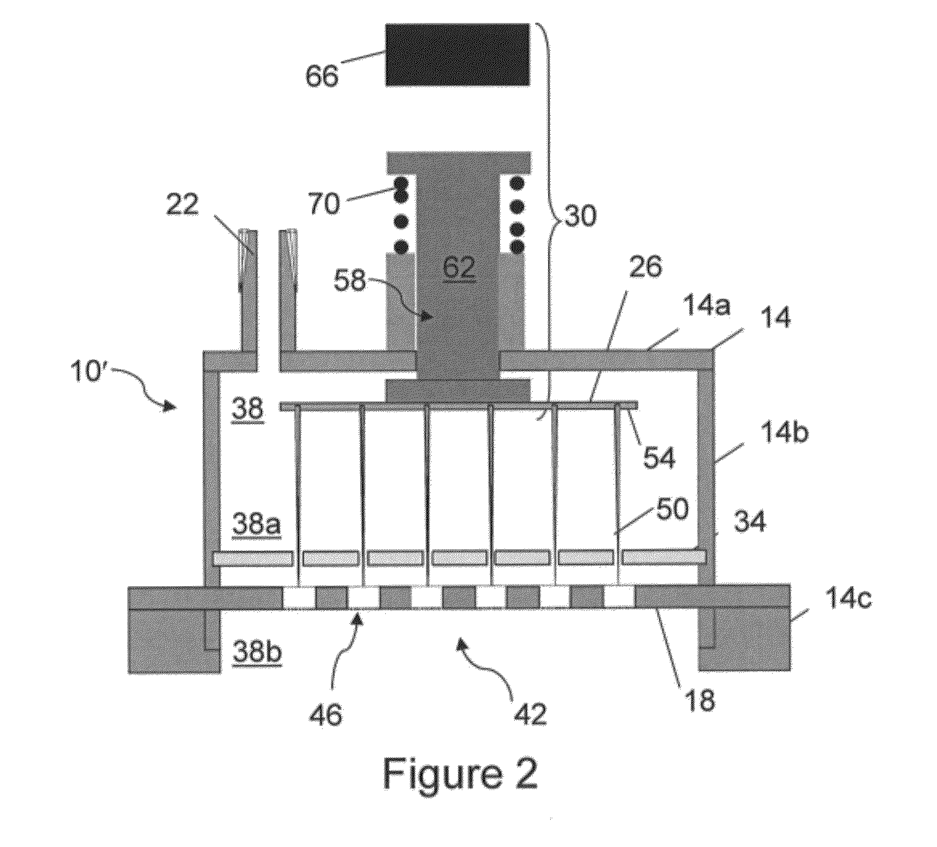
[0035]FIGS. 1 and 2 show apparatuses 10 and 10′, respectively, for deploying a needle array into skin. Apparatuses 10 and 10′ can be referred to as cartridges. Each apparatus includes a housing 14, a plate 18 disposed in the housing 14, a vacuum port 22, a needle array 26, an actuator mechanism 30. The needle array 26 is coupled to a source of RF energy. The apparatus can optionally include a needle guide 34.

[0036]The housing 14 defines a volume 38. The housing 14 includes a ceiling 14a and a wall 14b extending from the ceiling 14a. The wall 14b has an edge 14c for contacting the skin, and the edge 14c of the wall defines an aperture 42 in the housing 14. As illustrated in FIGS. 1 and 2, the ceiling 14a defines the vacuum port 22, which can be in fluid communication with a vacuum source. In certain embodiments, the wall 14b defines the vacuum port 22.

[0037]The plate 18 intersects the wall 14b and divides the volume 38 of the housing into two sub-volumes so that the wall 14b extends ...


PUM


Abstract

A skin treatment includes applying vacuum to draw skin into contact with a plate defining a plurality of holes, inserting a plurality of needles through the plurality of holes into the skin, and delivering RF energy via the plurality of needles to treat the skin.

Description

CROSS-REFERENCE TO RELATED APPLICATION[0001]This application claims the benefit of and priority to U.S. Provisional Patent Application No. 61 / 356,967 filed Jun. 21, 2010, which is owned by the assignee of the instant application and the disclosure of which is incorporated herein by reference in its entirety.FIELD OF THE INVENTION[0002]The invention relates generally to an array of needles held retracted in a protective cartridge. The array of needles can be deployed into the skin through a plate with the assistance of vacuum to effect a skin treatment using radio frequency (RF) energy.BACKGROUND[0003]U.S. Pat. No. 6,277,116 to Utely et al. discloses the use of microneedle arrays to shrink collagen by driving a multitude of needles into dermis and delivering RF energy. Utely also teaches the use of insulated needles to confine ohmic heating to the distal needle tip. However, this patent fails to address how to overcome the difficulties of preventing skin from being pushed out of the ...

Claims


Application Information

Patent Timeline
IPC IPC(8): A61N1/18
CPCA61B18/1477A61B2218/007A61B2017/00092A61B2017/00398A61B2018/00005A61B2018/00011A61B2018/0016A61B2018/00291A61B2018/00452A61B2018/00791A61B2018/00815A61B2018/00821A61B2018/00827A61B2018/00875A61B2018/00892A61B2018/126A61B2018/143A61B2018/1472A61B2018/1475A61B2218/002A61B2017/00088
Inventor SCHOMACKER, KEVIN
Owner CANDELA CORP
Why Eureka
Try Eureka