Cord end

a technology of cord ends and ends, which is applied in the direction of cables, buckles, mechanical devices, etc., can solve the problems of high material cost and cumbersome assembly of cord ends on the cord, and achieve the effect of simple and secure manner

Inactive Publication Date: 2012-06-28
DURAFLEX HONG KONG
View PDF14 Cites 1 Cited by
  • Summary
  • Abstract
  • Description
  • Claims
  • Application Information

AI Technical Summary

Benefits of technology

[0006]It is therefore an object of the invention to provide a cord end that consists of a single piece and which can be attached to the cord in a simple and secure manner.
[0007]The invention consists of a cord end having a main body having a bottom surface and a top surface and a covering portion attached to the main body that can be folded over the bottom surface and secured to the bottom surface. The main body has two cord-receiving apertures therein. Each aperture has a cord-securing slot in communication with the apertures, such that a cord is secured to the cord end by threading the cord from the bottom surface, through one aperture, across the top surface and through the other aperture and out the bottom surface, pulling the cord so that the cord slides out of the apertures and into the cord securing slots, and snapping the covering portion over the bottom surface. The free end of the cord can be trimmed prior to snapping the covering portion over the bottom surface, to prevent the cord from interfering with the operation of the covering portion. This particular arrangement of the cord as it is fed through the apertures creates two Z-shaped profiles from the cord. This particular profile prevents the cord from slipping once it has been fed into the main body and tightened.

Problems solved by technology

Thus, assembly of the cord ends on the cord is cumbersome and the material cost is high.

Method used


Image

  • Cord end
  • Cord end
  • Cord end

Examples


Embodiment Construction

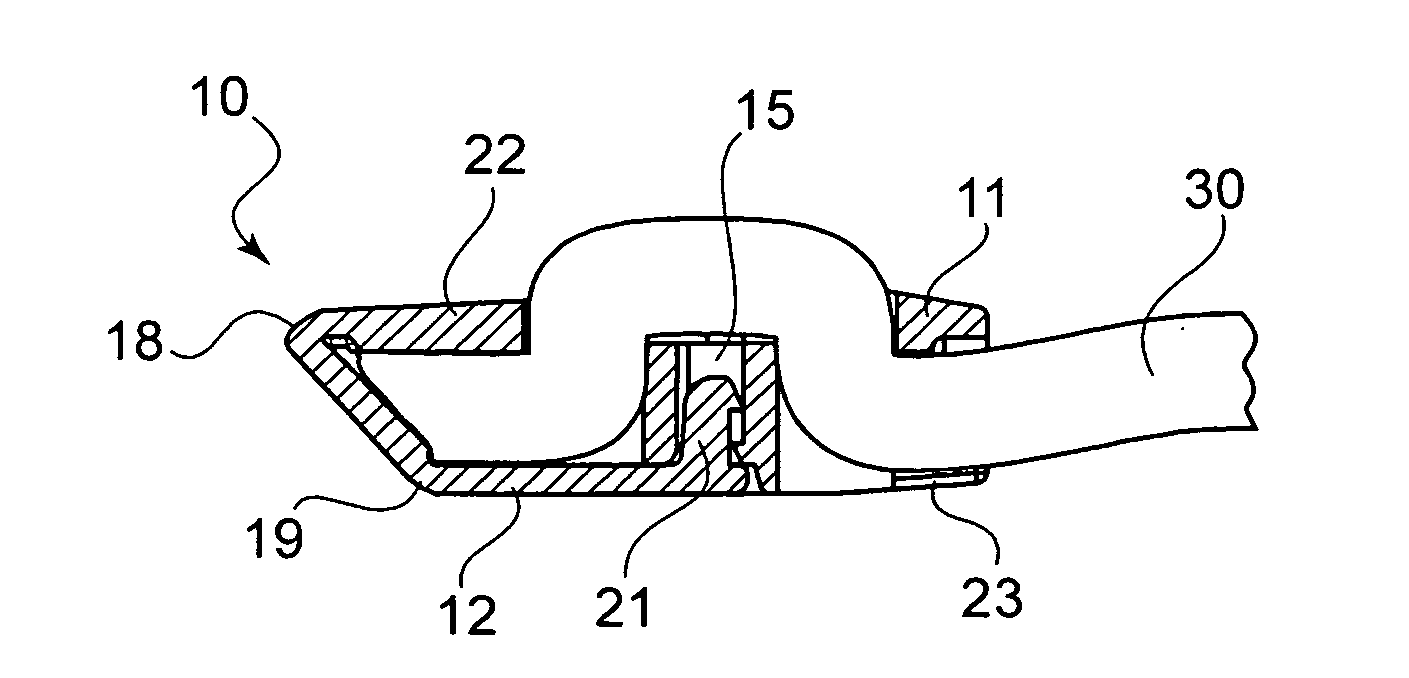
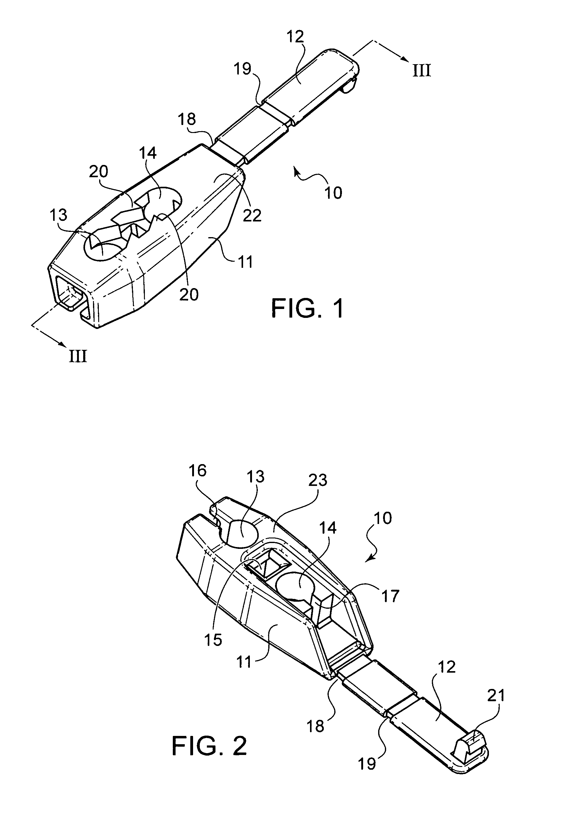
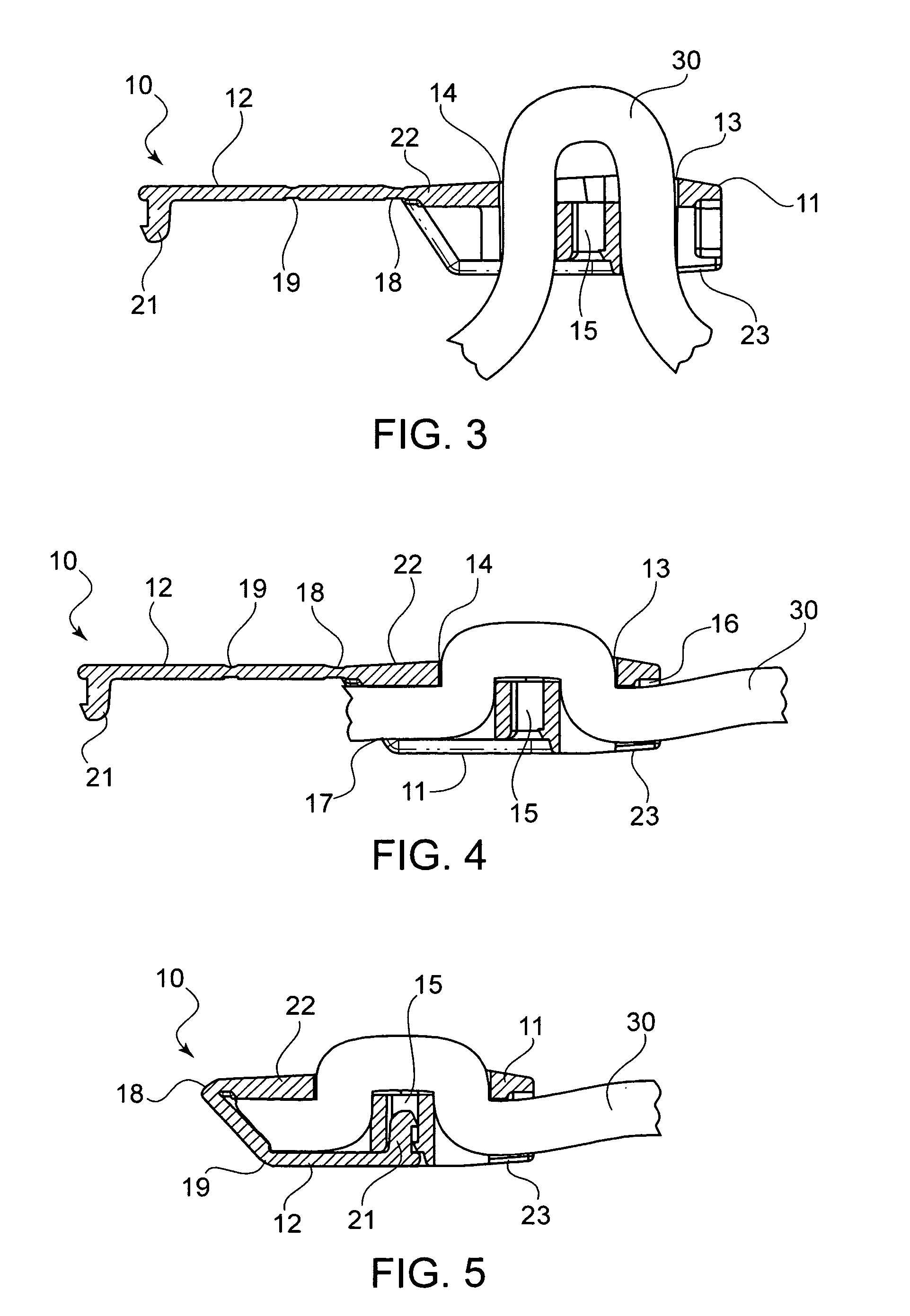
[0022]Referring now in detail to the drawings, a first embodiment of the cord end according to the invention is shown in FIGS. 1-5. Here, cord end 10 comprises a main body 11 with an attached covering portion 12. Main body 11 has two apertures 13, 14 that extend through the entire depth of main body 11. On the top surface 22 shown in FIG. 1 between apertures 13, 14 are a plurality of cord gripping teeth 20. On the bottom surface 23 shown in FIG. 2 is a groove 15 between apertures 13, 14. Covering portion 12 can be folded around and over the bottom surface 23 of main body 11, using hinges 18, 19, and then snapped into groove 15 with latch 21 to secure covering portion over the bottom surface 23 of main body 11, as shown in FIG. 5.

[0023]In use, as shown in FIGS. 3-5, a cord 30 is threaded from bottom surface 23, through aperture 13, across top surface 22, where it is gripped by teeth 20, and down through aperture 14. As shown in FIG. 4, at this point, cord 30 is pulled longitudinally ...


PUM


Abstract

A cord end has a main body with a bottom surface and a top surface and a covering portion attached to the main body that can be folded over the bottom surface and secured to the bottom surface. The main body has two cord-receiving apertures therein. Each aperture has a cord-securing slot in communication with the apertures, such that a cord is secured to the cord end by threading the cord from the bottom surface, through one aperture, across the top surface and through the other aperture and out the bottom surface, pulling the cord so that the cord slides into the cord securing slots, and snapping the covering portion over the bottom surface.

Description

BACKGROUND OF THE INVENTION[0001]1. Field of the Invention[0002]The present invention relates to a cord end. In particular, the present invention relates to a cord end that secures the end of a cord within the cord end and allows for simple assembly and use.[0003]2. The Prior Art[0004]Cord ends are used at the end of bungee and other cords to prevent fraying of the cords and to allow them to be pulled more easily. In general the cord is fed into the cord end and locked in place.[0005]Most cord ends are formed from two separate pieces that are snapped together to secure the end of the cord. Thus, assembly of the cord ends on the cord is cumbersome and the material cost is high.SUMMARY OF THE INVENTION[0006]It is therefore an object of the invention to provide a cord end that consists of a single piece and which can be attached to the cord in a simple and secure manner.[0007]The invention consists of a cord end having a main body having a bottom surface and a top surface and a coverin...

Claims


Application Information

Patent Timeline
Patent Type & Authority Applications(United States)
IPC IPC(8): F16B2/10
CPCF16G11/046Y10T24/4745F16G11/048
Inventor CHAN, YICK FAI
Owner DURAFLEX HONG KONG
Why Eureka
Try Eureka