Structural design with rear-ventilated cladding elements

a technology of rear ventilation and cladding, which is applied in the direction of special buildings, domestic heating, and door/window arrangements, etc., can solve the problems of dimensional deviation, corrosion protection and corrosion resistance of the rear ventilation of the cladding in the known construction, and achieve the effect of improving the protection against penetration

Active Publication Date: 2014-10-07
ASCHAUER JOHANN
View PDF20 Cites 2 Cited by
  • Summary
  • Abstract
  • Description
  • Claims
  • Application Information

AI Technical Summary

Benefits of technology

[0005]The invention is based on the object of providing a structural design with rear-ventilated cladding elements of the kind mentioned above, which in addition to proper rear ventilation offers improved protection against the penetration of fluids into the rear-ventilation area such as driving rain, a concentrated water jet during the cleaning of the elements or the like etc. The invention is especially suitable for creating structural designs which are open to the diffusion of vapor.
[0006]This object is achieved in accordance with the invention in such a way that at least the upper frame leg profile interior is assigned a splash guard which is in the manner of a labyrinth seal, adjoins the frame leg profile below the ventilation openings, covers the ventilation openings and preferably faces with the free end thereof towards the front of the cladding. These measures provide improved protection against the penetration of fluids into the rear-ventilation area in addition to proper rear ventilation. This is ensured especially by the splash guard provided in form of a labyrinth seal, at least in the upper frame leg. The splash guard must be dimensioned in such a way that it cannot be overcome by driving rain. A concentrated water jet such as occurs during the cleaning of the elements by means of a high-pressure cleaning device for example will be broken and deflected by the splash guard arranged in the manner of a labyrinth seal in such a way that although the fluid may partly penetrate the profile through the ventilation openings, it will be prevented by the splash guard to reach the rear-ventilation area behind the cladding element and will be guided out again via ventilation openings adjoining in the longitudinal direction of the frame leg profile. The supporting framework can also be a conventional house facade which may optionally need to be repaired and to which the rear-ventilated cladding elements are fixed. A structural design which is open to the diffusion of vapor can be created in this way in a simple manner by means of the invention. If the rear-ventilated cladding elements are or comprise active or passive solar collectors, the rear ventilation will prevent overheating of the modules, in particular of especially sensitive photovoltaic cells, in a simple and secure manner.
[0007]Especially simple constructional conditions for the splash guard are obtained when it is arranged in the manner of a C-profile which is directed with its opening against the front of the facade. The dimensioning of the individual distances between the profile and the splash guard is based on the respective purpose and is decided by the person skilled in the art. Furthermore, it is recommended that the ventilation openings are set back in relation to the front of the facade by approximately the thickness of the cladding elements in order to remove energy from the fluid prior to any penetration thereof.
[0009]Clean mounting conditions are obtained when the upper and preferably the lower frame leg profile form a receiving fold for the cladding elements, as a result of which the cladding elements are not only protected in a better way against damage but can also easily be attached to the substructure.
[0010]In this connection, the upper and lower frame leg profile can be assembled with peripheral frame leg profiles into a frame which is enclosed on the circumferential side, wherein the peripheral frame leg profiles are selectively only attached to the rear side of the cladding elements or additionally comprise a fold in which the cladding element is inserted. If the rear walls of the frame legs are additionally disposed in a common plane and if the frame is attached to a preferably gas-tight but vapor-permeable substructure, direct gas exchange between adjacent cladding elements can be avoided. Each cladding element is therefore only rear-ventilated itself and not additionally via adjacent cladding elements, which leads to an improved fire protection effect of the construction in accordance with the invention.
[0011]If insect screens which cover the ventilation channel cross-section are assigned to the upper and the lower frame leg profile in the ventilation channel opening into the rear-ventilation cross-section, it is not only possible to prevent the nesting of insects in the rear-ventilation area, but also to increase the security against the penetration of fluids into the rear-ventilation area by the screen.

Problems solved by technology

The punctiform fixing leads to the disadvantage in the known constructions that considerable alignment work is required for the individual cladding elements, because dimensional deviations in the prefabricated elements of the supporting constructions will add up during the mounting of the cladding elements with the unavoidable dimensional deviations in the building wall and in the supporting framework.
Furthermore, there are difficulties in protection from corrosion and in rear ventilation of the cladding in the known constructions.

Method used


Image

  • Structural design with rear-ventilated cladding elements
  • Structural design with rear-ventilated cladding elements
  • Structural design with rear-ventilated cladding elements

Examples


Embodiment Construction

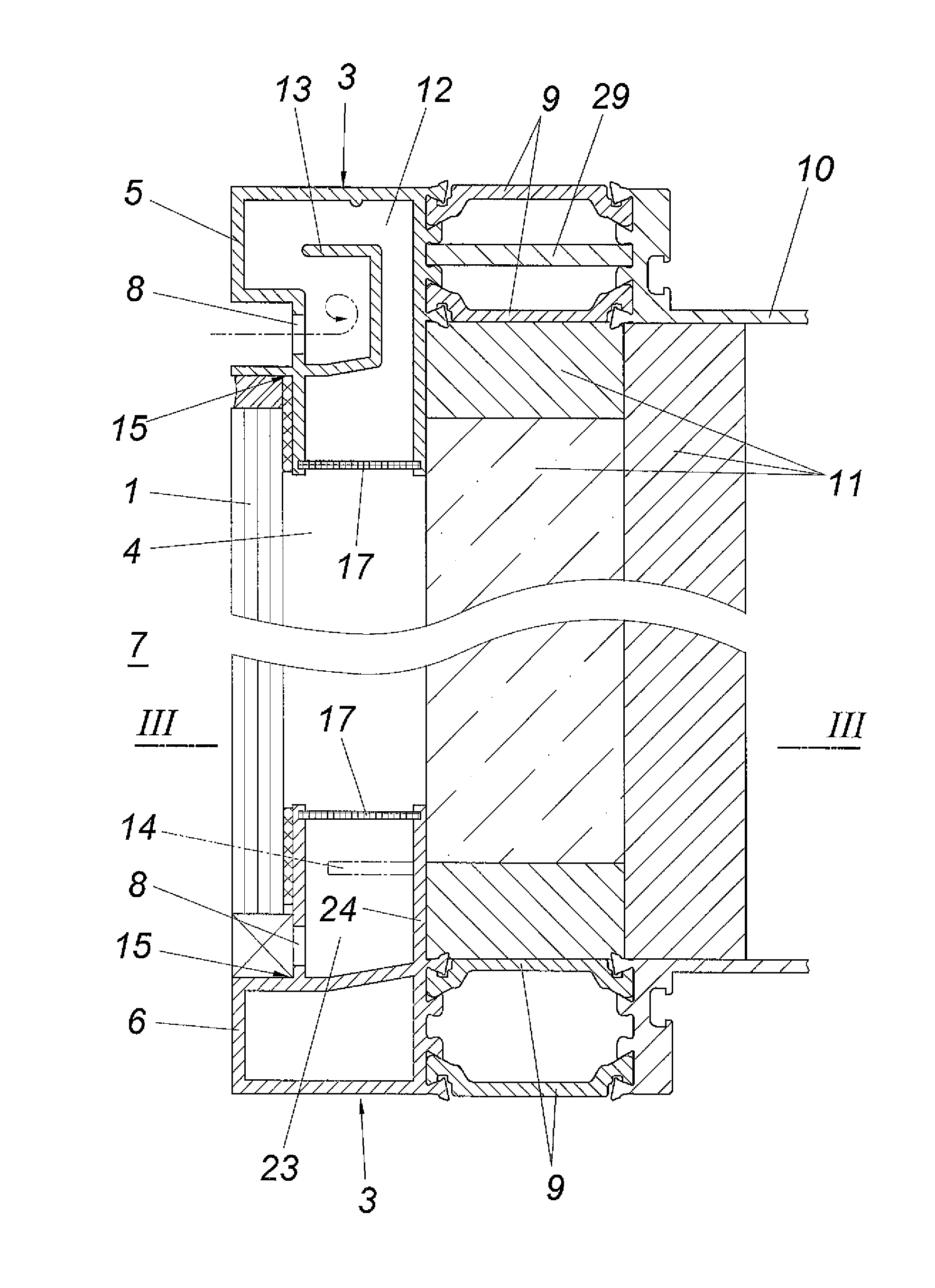
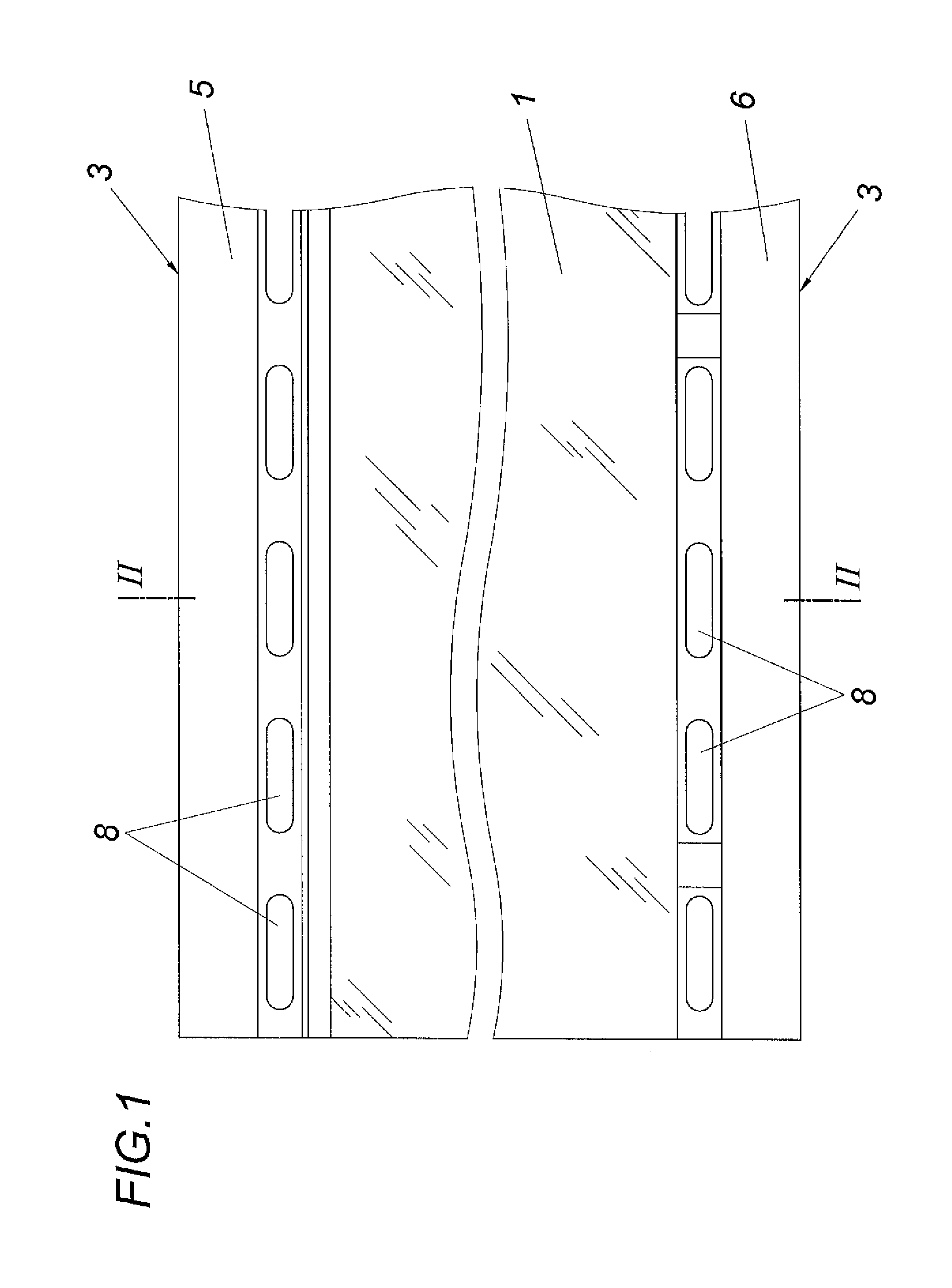
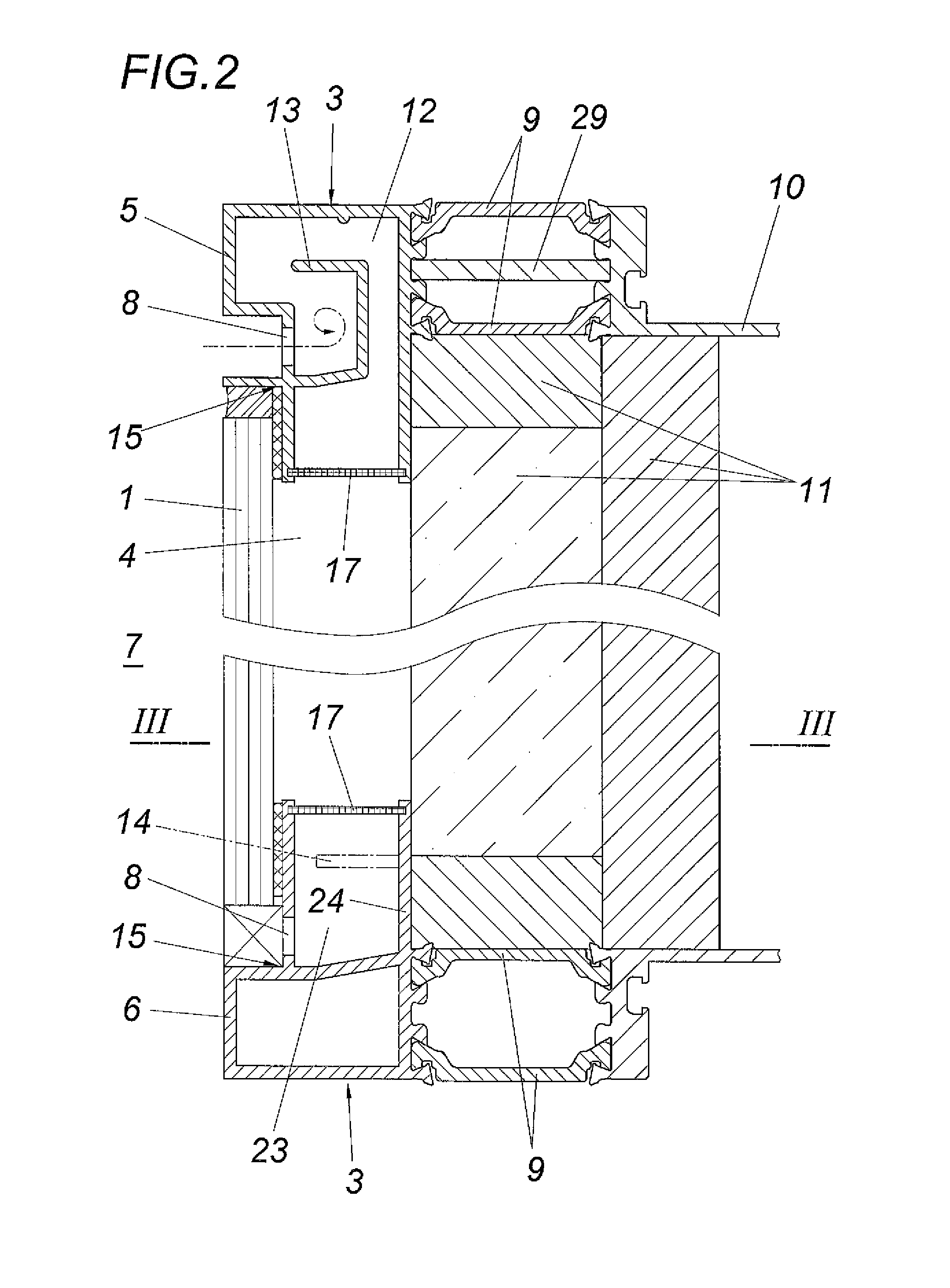
[0019]A structural design in accordance with the invention comprises at least one rear-ventilated cladding element 1, in particular a board, plate or a solar module, which can be suspended in front of a supporting framework 2 made of vertical support elements and horizontal bearing elements or a building wall. One frame 3 each is assigned to the cladding elements 1, which frame spans a rear-ventilation cross-section 4. Both the upper and the bottom frame leg profile 5, 6 of frame 3 comprise ventilation openings 8 opening towards the cladding front 7. The individual profiles of the frame 3 are attached to further profiles via insulating webs 9 in the illustrated embodiment, which further profiles can already be a part of the supporting framework 2 or still be part of the frame 3. In the illustrated embodiment according to FIG. 1 to FIG. 3, these profiles 10 are still parts of the frame 3, which in addition accommodates in its interior a substructure 11 consisting of various insulatin...


PUM


Abstract

A structural design is proposed, comprising rear-ventilated cladding elements (1), in particular plates or boards, which can be hung in front of a supporting framework (2), in particular consisting of vertical support elements and horizontal bearing elements, wherein the cladding elements are each assigned a frame (3) which spans a rear-ventilation cross-section (4) and the upper and lower frame leg profiles (5, 6) of which have ventilation openings (8) leading to the front (7) of the cladding. In order to provide advantageous rear-ventilation conditions it is proposed that at least the upper frame leg profile interior (12) is assigned a splash guard (13) which is arranged in the manner of a labyrinth seal, adjoins the frame leg profile below the ventilation openings (8), covers the ventilation openings (8) and preferably faces with the free end thereof towards the front (7) of the cladding.

Description

CROSS REFERENCE TO RELATED APPLICATIONS[0001]This application is the National Stage of PCT / AT2012 / 050020 filed on Feb. 8, 2012, which claims priority under 35 U.S.C. §119 of Austrian Application No. A 205 / 2011 filed on Feb. 16, 2011, the disclosure of which is incorporated by reference. The international application under POT article 21(2) was not published in English.BACKGROUND OF THE INVENTION[0002]The invention relates to a structural design with rear-ventilated cladding elements, in particular plates or boards, which can be hung in front of a supporting framework, in particular consisting of vertical support elements and horizontal bearing elements, wherein the cladding elements are each assigned one frame which spans a rear-ventilation cross-section and the upper and lower frame leg profiles of which have ventilation openings leading to the front of the cladding.DESCRIPTION OF THE PRIOR ART[0003]Claddings made of rear-ventilated plate-like cladding elements which are suspended ...

Claims


Application Information

Patent Timeline
Patent Type & Authority Patents(United States)
IPC IPC(8): F24F7/04E04B1/70E04B1/76E04F13/08E04B2/88E04F13/00F24F7/00F24F13/08F24S90/00
CPCE04B1/7076F24F2007/003E04F13/007F24J2/42Y02B10/20E04B2/88F24F13/08E04B1/7069E04B1/7612F24F7/04F24S20/66Y02E10/40F24F2007/0025F24S90/00Y02E10/44
Inventor ASCHAUER, JOHANN
Owner ASCHAUER JOHANN
Why Eureka
Try Eureka