
Length adjustable bicycle crank

a crank and bicycle technology, applied in the field of labor saving bicycles, can solve the problems of complex components, inability to save the force applied to the pedals while riding, and the number of drawbacks of the typical labor saving bicycl

Inactive Publication Date: 2012-07-05
CHEN KUNG CHENG +1
View PDF4 Cites 40 Cited by
  • Summary
  • Abstract
  • Description
  • Claims
  • Application Information

AI Technical Summary

Benefits of technology

[0008]It is therefore one object of the invention to provide a crank system mounted to a drive sprocket of a bicycle, comprising a crank arm secured to the drive sprocket and disposed at both sides thereof, the crank arm having two bent ends; and two telescopic assemblies each comprising a bar having one end fixedly secured to either end of the crank arm, the bar having a cross section of polygon, th

Problems solved by technology

However, most typical bicycles do not have adjustable crank arms and therefore, force applied to the pedals cannot be saved while riding.
However, a number of drawbacks have been found in the typical labor saving bicycle.
Its components are complicated and it is prone to malfunction.
Its operation is inconvenient.
It is not a lightweight mechanism and thus it can increase the weight of the bicycle greatly.
This compromises the desired purpose of labor saving when pedaling.

Method used


Image

  • Length adjustable bicycle crank
  • Length adjustable bicycle crank
  • Length adjustable bicycle crank

Examples


Embodiment Construction

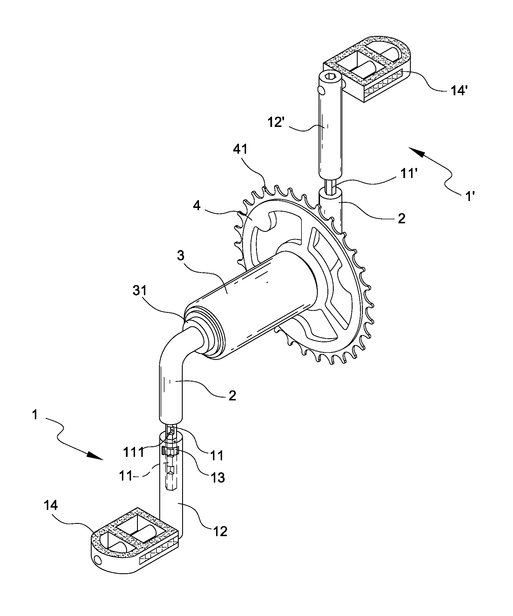
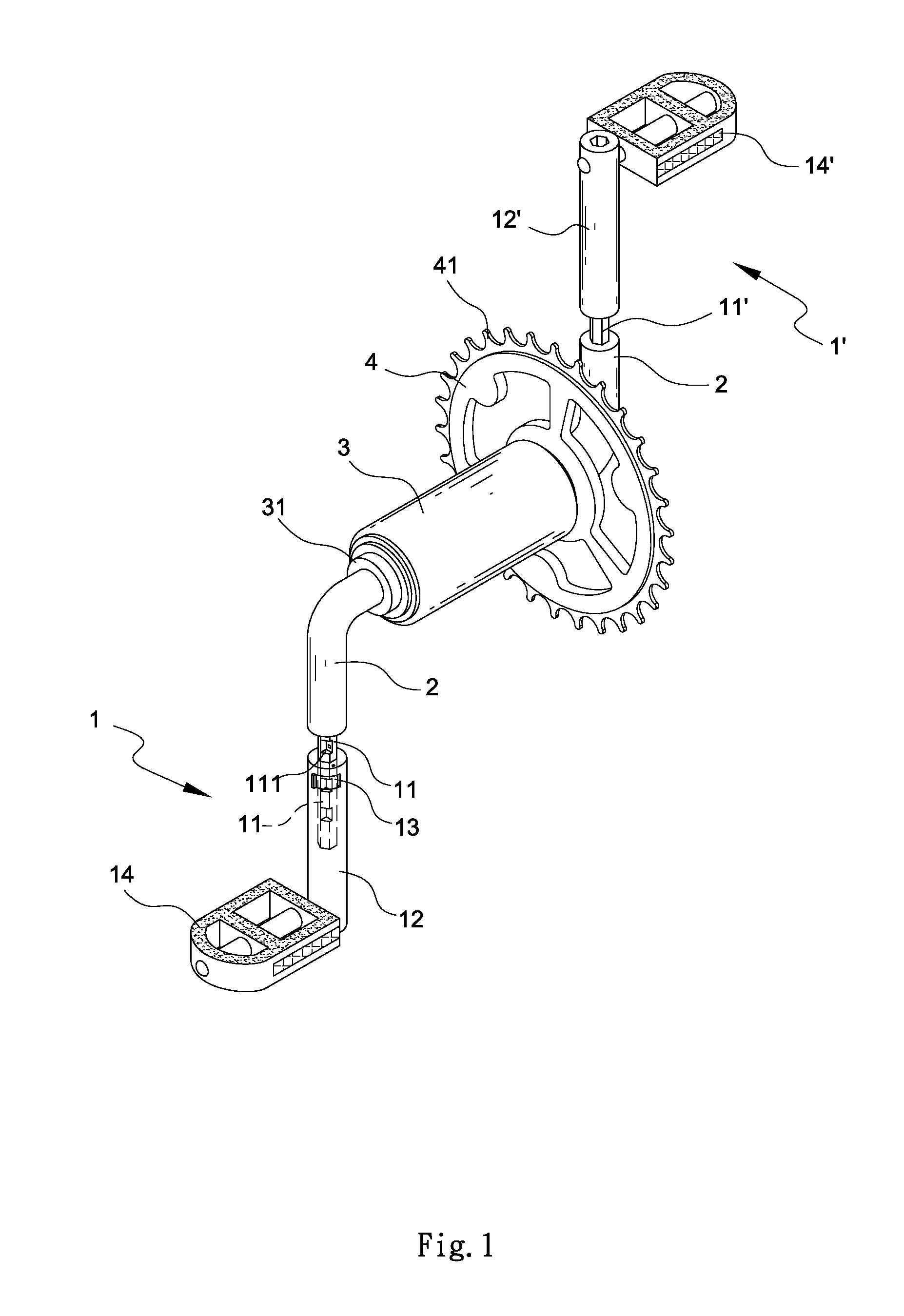
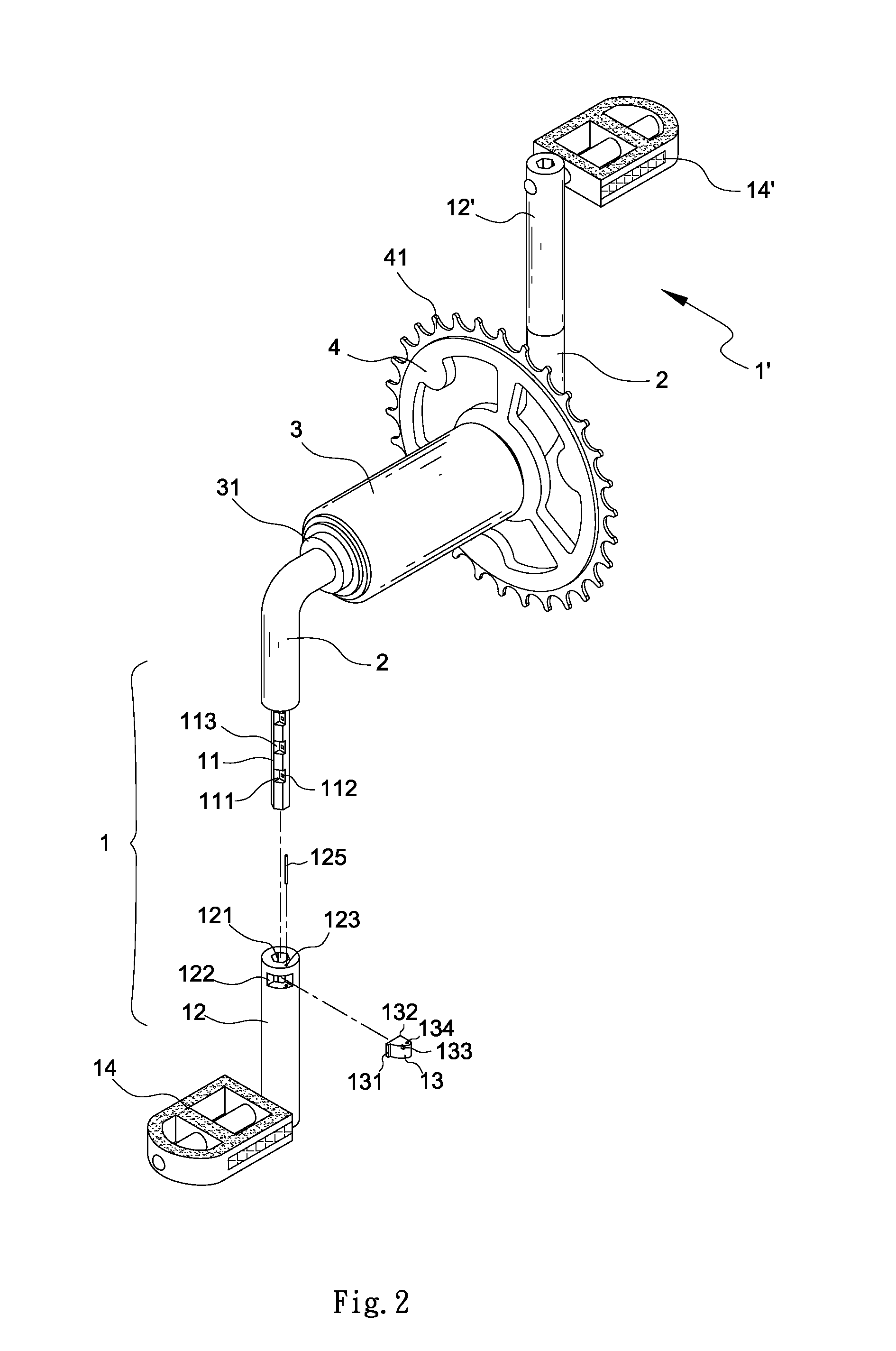
[0014]Referring to FIGS. 1 to 5, a crank system mounted to a drive sprocket of a bicycle in accordance with the invention is discussed in detail below.

[0015]Some components of the crank system (e.g., telescopic assemblies 1, 1′ each including a bar 11 (or 11′) and a sliding tube 12 (or 12′)) and pedals 14, 14′ are arranged symmetrically at both sides of a drive sprocket 4 and are mirror images each other. Thus, only telescopic assembly 1, pedal 14, and other components at one side of the drive sprocket 4 will be described hereinafter.

[0016]A telescopic assembly 1 comprises a bar 11 and a sliding tube 12 slidably put on the bar 11. One end of the bar 11 is fixedly secured to one of two bent ends of a crank arm 2. Two spaced externally threaded sections 21 are provided on the horizontal part of the crank arm 2. One externally threaded section 21 is secured to a central crank support of the drive sprocket 4 having a series of teeth 41 therearound. A cylindrical sleeve 3 comprises two n...


PUM


Abstract

A crank system mounted to a drive sprocket of a bicycle includes a crank arm secured to the drive sprocket and disposed at both sides thereof, the crank arm having two bent ends; and two telescopic assemblies each comprising a bar having one end fixedly secured to either end of the crank arm, the bar having a cross section of polygon, the bar including a plurality of longitudinal notches, a sliding tube slidably put on the bar, the sliding tube including a surface opening communicating with the bar, and a pivotal lock member in the surface opening, the lock member being adapted to either dispose in one of the notches in a locked position of the telescopic assembly or clear the notch in a unlocked position of the telescopic assembly. This length adjustable bicycle crank system can save force when pedaling.

Description

BACKGROUND OF THE INVENTION[0001]1. Field of Invention[0002]The invention relates to labor saving bicycles and more particularly to a bicycle having two cranks each adapted to adjust the length (e.g., length increase) so as to save force when pedaling.[0003]2. Description of Related Art[0004]A bicycle is a vehicle having two wheels placed one behind the other and mounted on a frame which carries a saddle for a rider. Between the wheels is a crank-axle which the rider drives by means of the cranks and pedals, and its motion is transmitted to the rear wheel by a chain passing over two drive sprockets, one fixed on the crank-axle and the other on the hub of the rear wheel. The rear wheel is usually so arranged that it can turn, when the bicycle is running by its own momentum, independently of the chain and pedals. The front wheel is mounted in a fork having its two upper ends brazed into the “crown,” to which also the lower end of the steering tube is brazed. The steering tube is mount...

Claims


Application Information

Patent Timeline
IPC IPC(8): B62M3/02
CPCY10T74/2165B62M3/02
Inventor CHEN, KUNG-CHENGLUKE, WALTER
Owner CHEN KUNG CHENG
Learn More