Ring Cutter for Twine or the Like

Inactive Publication Date: 2012-07-19
HANDY TWINE KNIFE
View PDF28 Cites 6 Cited by
  • Summary
  • Abstract
  • Description
  • Claims
  • Application Information

AI Technical Summary

Benefits of technology

[0010]The ring cutter of the present invention comprises a ring having a pair of flexible and resilient side portions that are connected at the upper end thereof and separated at the lower end thereof by a space therebetween, An upstanding bracket is secured to the upper end of the ring and a cutting blade is secured to the bracket and extends forwardly from the ring in generally parallel relation to the longitudinal axis of the ring. The upper end of the ring may be offset rearwardly from the lower split end thereof to enable the ring to fit more comfortably on a finger of a user, such as the little finger.
[0012]In the event the ring or cutting blade should become caught or jammed in an adjacent device or piece of machinery or the like, the user can pull his or her finger against the lower spaced ends of the side portions of the ring to cause them to separate and allow the finger of the user to be easily removed from the ring to prevent injury to the finger or hand of the user.
[0013]In a modified embodiment, the lower spaced ends of the side portions of the ring are connected by a narrow tab that can be cut or otherwise broken to allow the lower spaced ends to separate. This embodiment will allow a user to use the ring with the lower spaced ends being connected or being separated.

Problems solved by technology

1. They have been complicated in construction and thus expensive to manufacture;
2. They have been uncomfortable on a finger of a user; and / or
3. They have been difficult to remove quickly from the finger of a user in cases where the cutter is inadvertently retained or caught in an adjacent device, piece of equipment or the like.

Method used


Image

  • Ring Cutter for Twine or the Like
  • Ring Cutter for Twine or the Like
  • Ring Cutter for Twine or the Like

Examples


second embodiment

[0031]In the ring cutter shown in FIGS. 5 and 6, the lower ends of the side portions 14 of the ring 12 may be provided with legs 26 of any suitable construction to enable the ring cutter 10 to be supported in an upright manner on a support surface S (FIG. 6). As shown in FIG. 5, the legs 26 may be in the form of generally cylindrical members formed integrally with the side portions 14 of the ring member 12 or secured thereto in any suitable manner.

[0032]In the use of the ring cutter 10 of the present invention, the ring 12 may be positioned on the inner end of a finger of the user, such as the little finger, with the cutting blade 20 extending forwardly. The cutting blade 20 can then be used to cut twine, thread or any other material by appropriate movement of the finger or hand of the user. The ring cutter 10 of the present invention is especially useful, for example, by persons who tie up bundles, packages or the like with twine or the like. The separation of the lower ends of the...

third embodiment

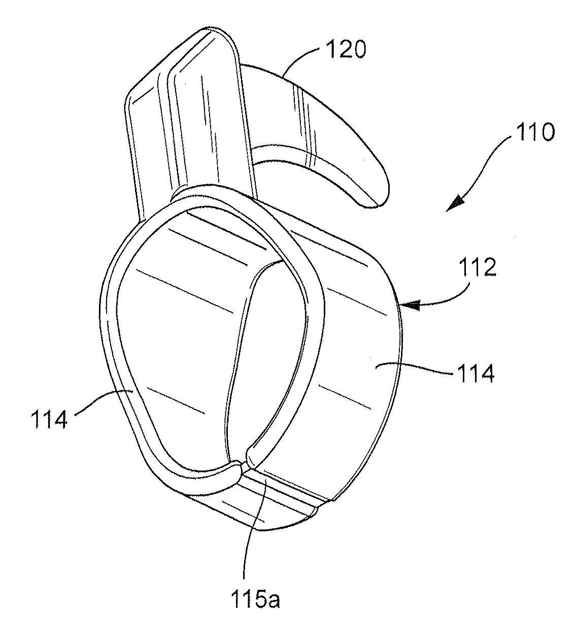
[0033]In the ring cutter 110 shown in FIGS. 7-9, the lower spaced ends of the side portions 114 of the ring 112 are connected by a narrow tab 115 which can be cut or otherwise broken to allow the spaced ends to separate at 116 as shown in FIG. 9 at the option of a user. Alternatively, the tab 115 may be frangible so that it will break when a sufficient force is applied to it by a user, either voluntarily or in response to a force applied to it in the event the ring 112 or cutting blade 120 becomes caught or jammed in an adjacent device or piece of machinery. The tab 115 may be of any suitable size and shape. For example the tab 115a may be of the same size as the side portions 114 as shown in FIG. 10.

[0034]Because of the simple construction of the ring cutter 10, it may be molded in one piece construction to enable it to be simple and inexpensive to manufacture. It may also be constructed in any other suitable manner.


PUM


Abstract

A ring cutter for twine or the like, comprising a ring adapted to fit on the finger of a user and having a pair of side portions joined at the upper end thereof and separated at the lower end thereof by a space therebetween. The ring is formed of a flexible and resilient material. A bracket extends upwardly from the upper portion of the ring and a cutting blade is secured to the bracket and extends forwardly therefrom. The lower ends of the side portions of the ring are separable to enable a finger of a user to be removed from the ring through the space between the side portions by the application of a downward force by the finger on the lower ends of the side portions. The lower ends may be connected by a narrow tab that can be cut or is frangible.

Description

CROSS REFERENCE TO RELATED APPLICATION[0001]This application is a continuation-in-part of application Ser. No. 12 / 379,020 filed on Feb. 11, 2009.BACKGROUND OF THE INVENTION[0002]1. Field Of The Invention[0003]The present invention relates to a cutter for twine or the like and, more particularly, to a new and improved cutter in the form of a ring which fits on the finger of a user.[0004]2. Description of Related Art[0005]Although cutters for twine or the like in the form of a ring that can be worn on a finger have been in use for many years and have generally served their purpose, they have been subject to one or more of the following disadvantages:[0006]1. They have been complicated in construction and thus expensive to manufacture;[0007]2. They have been uncomfortable on a finger of a user; and / or[0008]3. They have been difficult to remove quickly from the finger of a user in cases where the cutter is inadvertently retained or caught in an adjacent device, piece of equipment or the...

Claims


Application Information

Patent Timeline
IPC IPC(8): B26B27/00
CPCB26B27/007
Inventor CALDWELL, BRIAN L.TSCHANTZ, JOEL D.
Owner HANDY TWINE KNIFE
Why Eureka
Try Eureka