Combination hook rack
- Summary
- Abstract
- Description
- Claims
- Application Information
AI Technical Summary
Benefits of technology
Problems solved by technology
Method used
Image

Examples
first embodiment
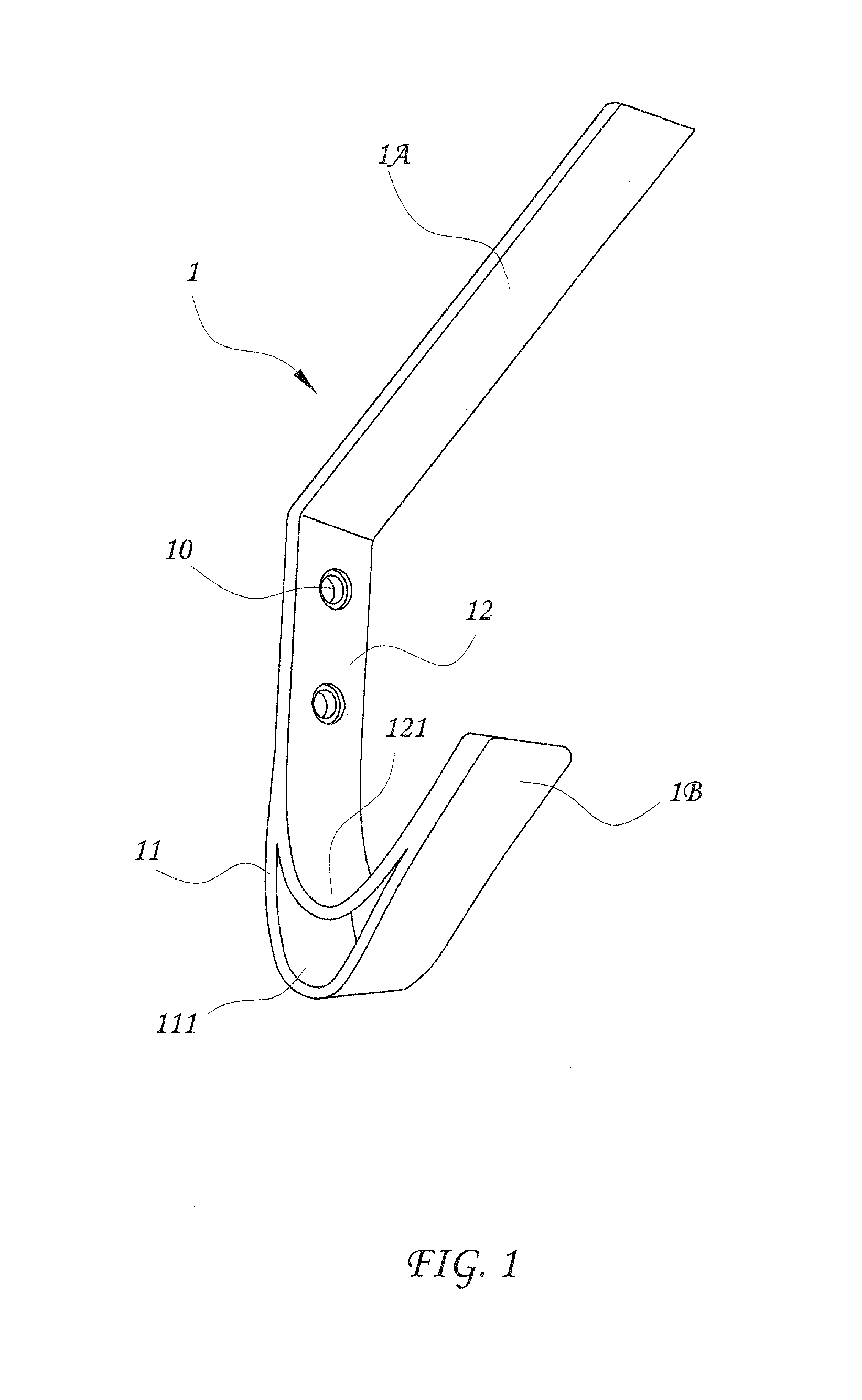
[0018]Referring to FIG. 1, a hanging hook 1 for combination hook rack in accordance with the present invention is formed of a first flat bar 11 and a second flat bar 12. The first flat bar 11 and the second flat bar 12 are bonded together and then bent into a predetermined shape having an obliquely forwardly tilted straight upper part 1A and a hooked lower part 1B where a part of the first flat bar 11 forms a first hanging portion 111 on the middle of the hooked lower part 1B, and a part of the second flat bar 12 forms a second hanging portion 121 on the middle of the hooked lower part 1B and spaced above the first hanging portion 111. Thus, an open space is transversely formed in the hooked lower part 1B between the first hanging portion 111 and the second hanging portion 121. Further, the obliquely forwardly tilted straight upper part 1A can be made relatively longer than the hooked lower part 1B. Alternatively, the obliquely forwardly tilted straight upper part 1A can be made rel...
second embodiment
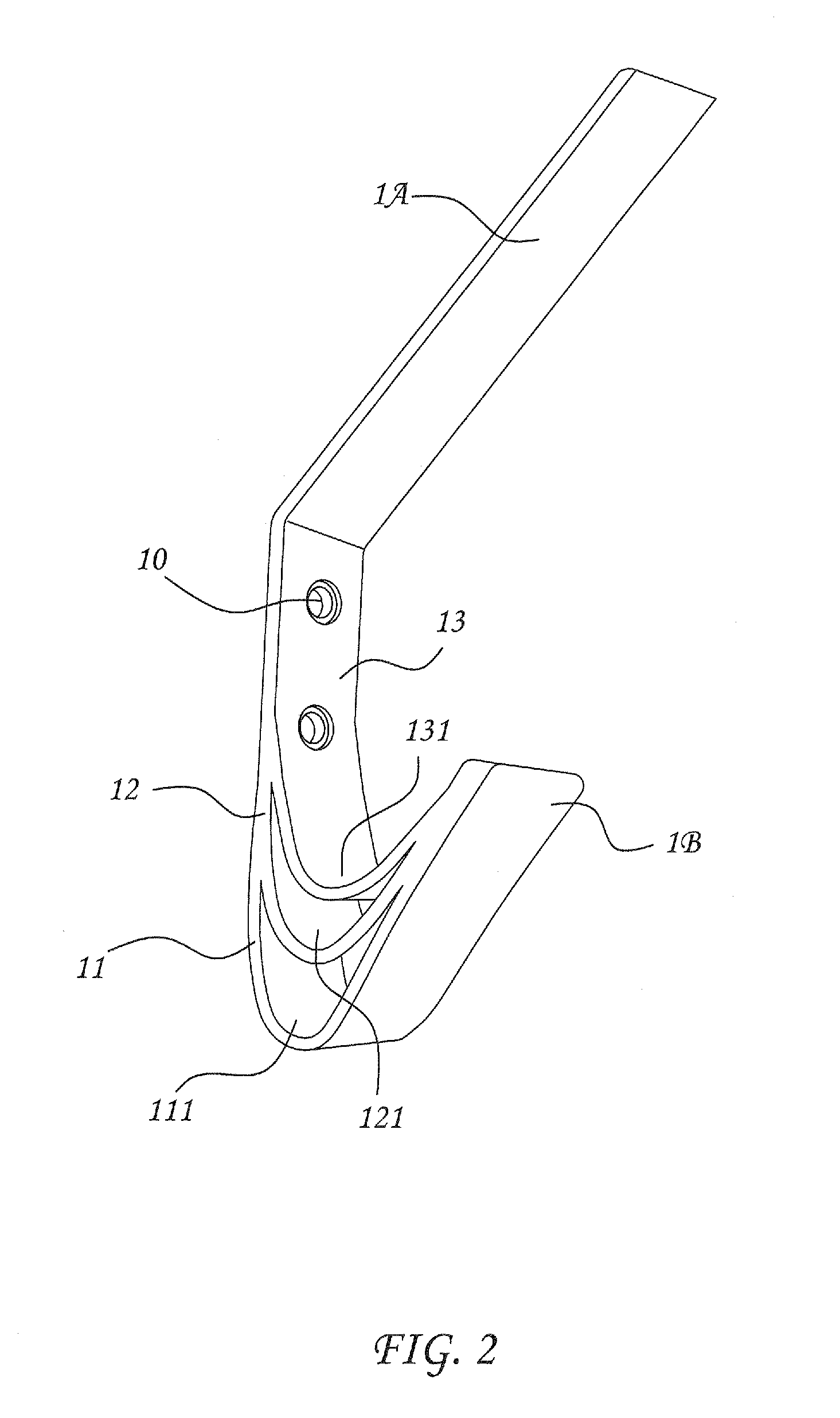
[0019]FIG. 2 illustrates a hanging hook 1 for combination hook rack in accordance with the present invention, which is formed of a first flat bar 11, a second flat bar 12 and a third flat bar 13. The first flat bar 11, the second flat bar 12 and the third flat bar 13 are bonded together and then bent into a predetermined shape having an obliquely forwardly tilted straight upper part 1A and a hooked lower part 1B where a part of the first flat bar 11 forms a first hanging portion 111 on the middle of the hooked lower part 1B, a part of the second flat bar 12 forms a second hanging portion 121 on the middle of the hooked lower part 1B and spaced above the first hanging portion 111, and a part of the third flat bar 13 forms a third hanging portion 131 on the middle of the hooked lower part 1B and spaced above the second hanging portion 1231. Thus, an open space is transversely formed in the hooked lower part 1B between each two adjacent ones of the first hanging portion 111, second han...
third embodiment
[0020]FIG. 3 illustrates a hanging hook 1 for combination hook rack in accordance with the present, which is formed of a first flat bar 11 and a second flat bar 12. The first flat bar 11 and the second flat bar 12 are bonded together and then bent into a predetermined shape having an obliquely forwardly tilted hooked lower part 1B where a part of the first flat bar 11 forms a first hanging portion 111 on the middle of the hooked lower part 1B, and a part of the second flat bar 12 forms a second hanging portion 121 on the middle of the hooked lower part 1B and spaced above the first hanging portion 111. Thus, an open space is transversely formed in the hooked lower part 1B between the first hanging portion 111 and the second hanging portion 121. Further, the hanging hook 1 can be processed to provide mounting through holes 10 at suitable locations for mounting.
PUM
 Abstract
Description
Claims
Application Information
 - R&D Engineer
- R&D Manager
- IP Professional
- Industry Leading Data Capabilities
- Powerful AI technology
- Patent DNA Extraction
Browse by: Latest US Patents, China's latest patents, Technical Efficacy Thesaurus, Application Domain, Technology Topic.
© 2024 PatSnap. All rights reserved.Legal|Privacy policy|Modern Slavery Act Transparency Statement|Sitemap