Firearm handguard system

Active Publication Date: 2012-07-26
TROY INDUSTRIES
View PDF15 Cites 97 Cited by
  • Summary
  • Abstract
  • Description
  • Claims
  • Application Information

AI Technical Summary

Problems solved by technology

The problems faced by a free floating handguard

Method used


Image

  • Firearm handguard system
  • Firearm handguard system
  • Firearm handguard system

Examples


Embodiment Construction

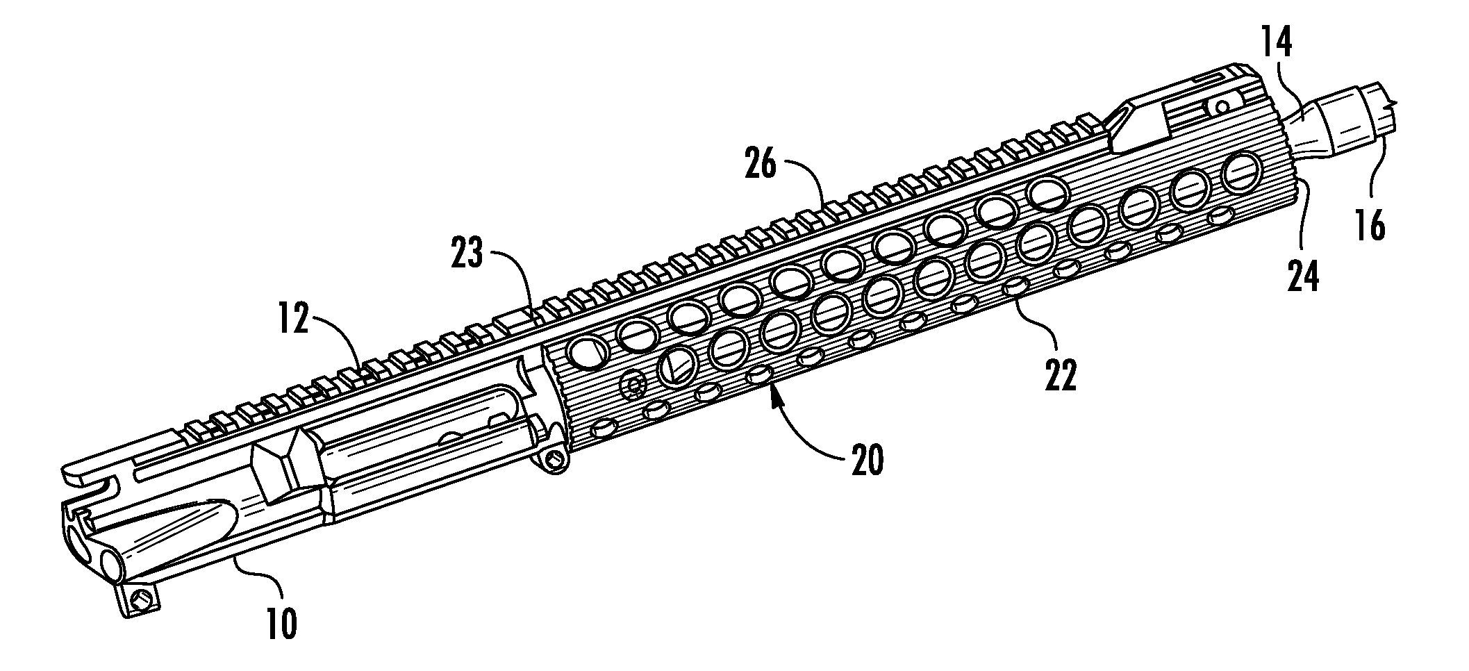
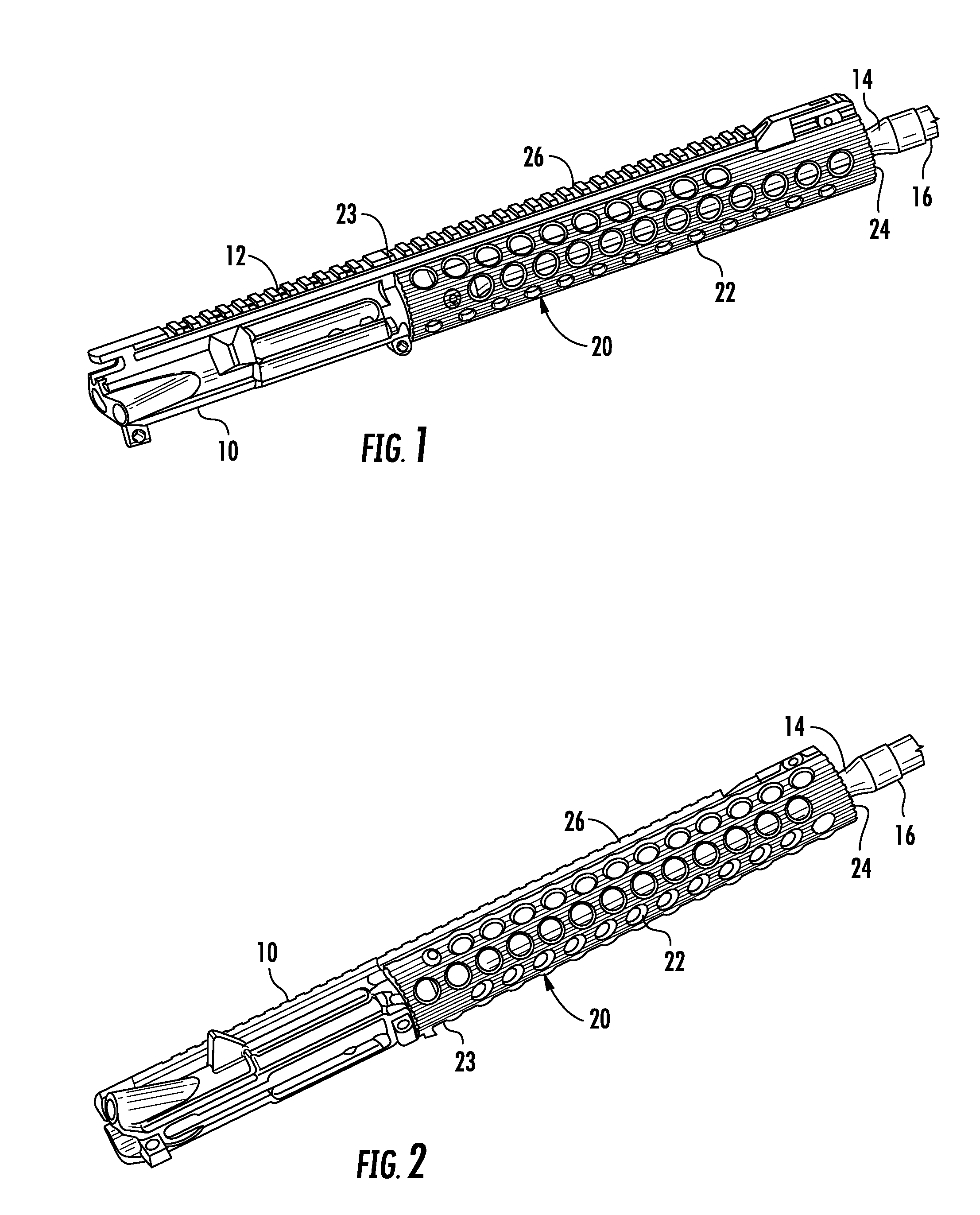
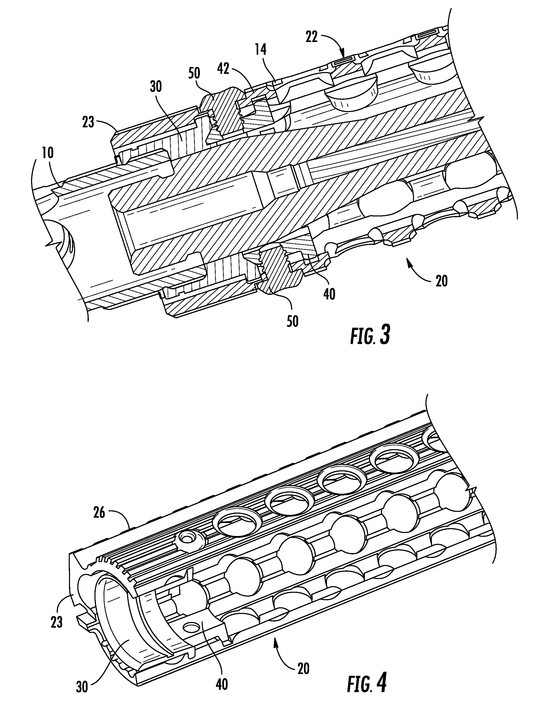
[0023]Turning now to the drawings in which like reference characters indicate corresponding elements throughout the several views, attention is directed to FIGS. 1 and 2 which illustrate a receiver 10 having a rail 12 formed on an upper surface thereof, a barrel 14 extending from receiver 10 and terminating in a muzzle 16, and a handguard system generally designated 20 coupled thereto. Handguard system 20 includes a tubular body 22 having a rearward end 23 and a forward end 24. It will of course be understood that the cross-section could be oval, square, rectangular, or any cylindrical configuration but primarily is hollow or tubular so as to surround at least a portion of the barrel of a firearm without coming in contact therewith along the length of the barrel that is surrounded. For reasons that will become apparent presently, a handguard with a round cross-section is preferred because it is the simplest to form and manufacture. A rail 26 can be formed along a top surface of tubu...


PUM


Abstract

A clamping mechanism for attaching a handguard to a firearm includes a barrel nut having radially outwardly directed tines, a tubular body having a plurality of longitudinal grooves separated by lands forming an inner surface of the tubular body, and a pair of circumferentially extending grooves traversing the lands, formed forward from a rearward end of the tubular body. A clamp element is carried by the tubular body and includes a body with a beveled end and a heel extending substantially perpendicularly from an opposing end of the body. The clamp element is adjustably positioned within the tubular body with the heel extending radially outwardly and received in the second groove and the beveled end engages the barrel nut.

Description

CROSS-REFERENCE TO RELATED APPLICATIONS[0001]This application claims the benefit of U.S. Provisional Application No. 61 / 432,742 filed 14 Jan. 2011.FIELD OF THE INVENTION[0002]This invention relates to firearms.[0003]More particularly, the present invention relates to handguards for use on firearms.BACKGROUND OF THE INVENTION[0004]In the field of firearms, handguards are ubiquitous and ever changing. Originally, handguards were used to provide something to grasp while firing the weapon. The handguard provided a comfortable grip and protected the user's hands from the heat of the barrel. Over the years, methods of attachment of handguards and additions to the handguard have been developed to prevent adverse effect to accuracy and provide attachment points for accessories. Free floating handguards have been found to provide firearms with the best accuracy by eliminating flexing or warping of the barrel. The problems faced by a free floating handguard are maintaining sufficient rigidity...

Claims


Application Information

Patent Timeline
IPC IPC(8): F41C23/00F41A21/48
CPCF41G11/003F41C23/16
Inventor TROY, STEPHEN P.HEWES, DAVID A.
Owner TROY INDUSTRIES
Why Eureka
Try Eureka