Paper detecting device and printer including the same

a detection device and paper detector technology, applied in the direction of measuring devices, printing, instruments, etc., can solve the problems of paper detectors that cannot be held at a predetermined stop position reliably, move the paper detectors, and difficult to precisely stop the paper detectors at a desired position, etc., to achieve smooth movement and simple operation

Active Publication Date: 2012-07-26
CITIZEN SYST JAPAN +1
View PDF4 Cites 5 Cited by
  • Summary
  • Abstract
  • Description
  • Claims
  • Application Information

AI Technical Summary

Benefits of technology

[0016]An object of the present invention is to provide a paper detecting unit and a paper detecting device incorporating the paper detecting unit which can surely stop or fix the paper detecting unit at a desired stop position, and smoothly move it by a simple operation when needed and provide an operator an indication for a proper stop position.

Problems solved by technology

However, the device disclosed in Reference 1 faces a problem that it is difficult to precisely stop the paper detector at a desired position since applied with an initial force to move the paper detector in a still state, it may be moved too far unexpectedly.
Meanwhile, if the elastic element is set to have a small friction, an operator's careless touch may easily move the paper detector and the paper detector cannot be held at a predetermined stop position reliably.
However, this may cause another problem that with no indication or marks for stop positions provided, the operator cannot know the right position to stop the detector so that he or she operates it only by his / her experience or intuition and the desired position at which the operator has stopped the detector may not be actually the right stop position originally set in the device.
However, with the concave and the protrusion strongly engaged, the paper detector cannot be smoothly moved when applied with an operational force.
In addition, once it starts moving, it may be moved too far, passing over a target stop position.
Meanwhile, when the engagement is weak, the paper detector may be unintentionally moved by unexpected contact with another element or an operator's finger or else.

Method used


Image

  • Paper detecting device and printer including the same
  • Paper detecting device and printer including the same
  • Paper detecting device and printer including the same

Examples


Embodiment Construction

[0027]Hereinafter, embodiments of a printer and a paper detecting device according to the present invention will be described in detail with reference to the accompanying drawings. Wherever possible, the same reference numbers will be used throughout the drawings to refer to the same or like parts.

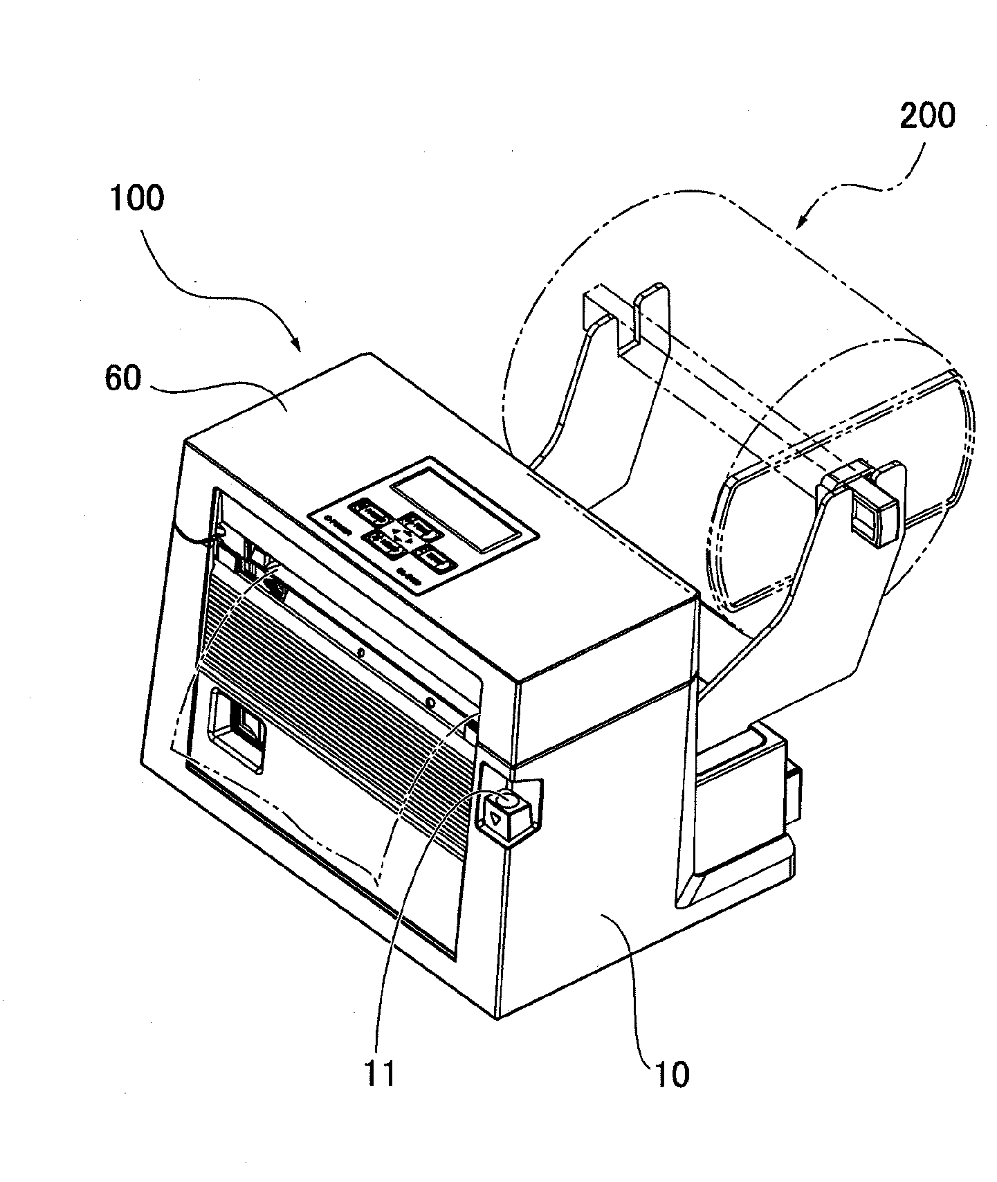
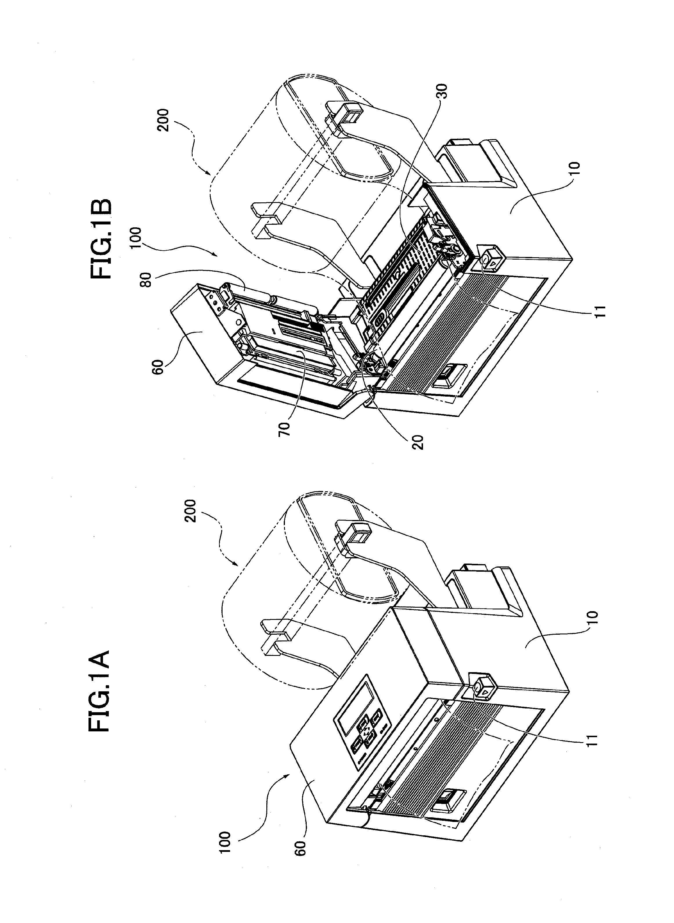
[0028]FIGS. 1A, 1B are perspective views of a thermal printer 100 as a printer according to one embodiment of the present invention. With an open / close button 11 on a printer body 10 pressed, a cover 60 is opened sideways as shown in FIG. 1B for replacing a roll paper 200 disposed between the printer body 10 and the cover 60 or maintenance purposes such as inspection or replacement of parts and components inside the printer body 10 and the cover 60.

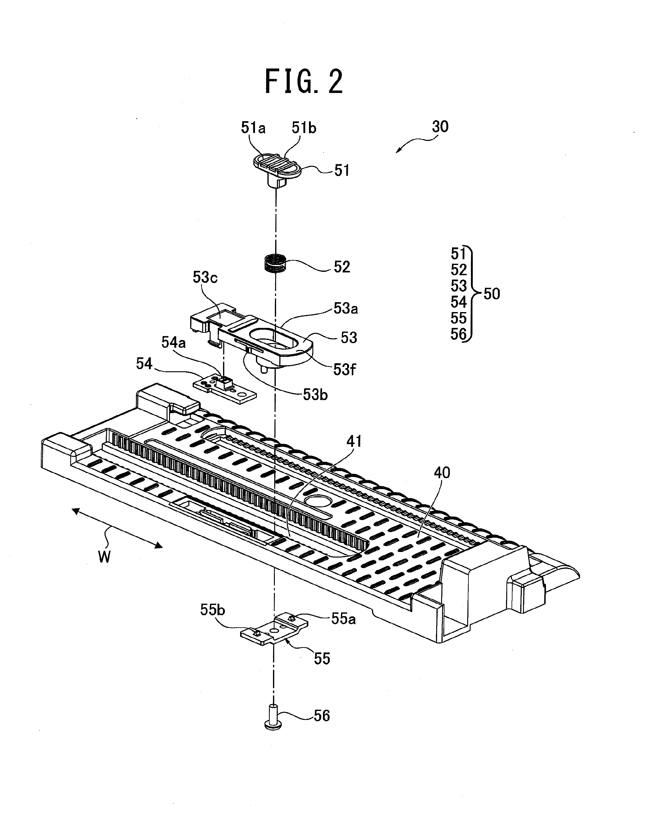
[0029]The printer body 10 includes a paper detecting device 30 having a platen roller 20 and a transmissive type optical sensor (54a in FIG. 2) for detecting the roll paper 200.

[0030]The cover 60 includes a thermal print head 70 in a portion opp...


PUM

PropertyMeasurementUnit
forceaaaaaaaaaa
widthsaaaaaaaaaa
widthaaaaaaaaaa

Abstract

A paper detecting device includes a paper detecting element, and a guide element having a path along which the paper detecting element is moved, in which at least one of the engaging element and the guide element includes an engaging element configured to be movable between an engaging position at which the paper detecting element is fixed on the path and a release position at which the paper detecting element is released from the fixation, and a click generator configured to click when the paper detecting element is moved on the path to reach a right position to stop.

Description

CROSS REFERENCE TO RELATED APPLICATION[0001]The present application is based on and claims priority from Japanese Patent Application No. 2011-10868, filed on Jan. 21, 2011, the disclosure of which is hereby incorporated by reference in its entirety.BACKGROUND OF THE INVENTION[0002]1. Field of the Invention[0003]The present invention relates to a paper detecting device and a printer incorporating the paper detecting device, particularly to an improvement in a movable paper detecting device.[0004]2. Description of the Prior Art[0005]A printer generally includes a paper detecting device to detect a paper and paper reference positions in order to properly set paper feed timing and print start / end timing and print information on the paper at the right position while feeding the paper.[0006]This paper detecting device includes a paper detector such as a reflective or transmissive type optical sensor. When mounted in a printer in which papers in different widths are selectively used, the p...

Claims


Application Information

Patent Timeline
Patent Type & Authority Applications(United States)
IPC IPC(8): G01N21/59
CPCB41J11/0095
Inventor MATSUSHIMA, GEN
Owner CITIZEN SYST JAPAN
Why Eureka
Try Eureka