Tidal power generating module and tidal power generation method using the same

a technology of tidal power generation and generating module, which is applied in the direction of electric generator control, machines/engines, mechanical equipment, etc., can solve the problems of difficult dam maintenance, high cost, and poor ecosystem, and achieve economic and stably generating power

Inactive Publication Date: 2012-08-02
KIM JUNG SUK +1
View PDF19 Cites 8 Cited by
  • Summary
  • Abstract
  • Description
  • Claims
  • Application Information

AI Technical Summary

Benefits of technology

[0009]Therefore, the present invention has been made in view of the above problems, and it is an object of the present invention to provide a tidal power generating module that is capable of economically and stably generating power using tidal force, which is a permanent energy source, and a tidal power generating method using the same.
[0010]It is another object of the present invention to provide a tidal power generating module that is capable of continuously generating power using compressed air and weight of seawater even at high tide and low tide at which the level of the seawater is not fluctuated in addition to the vertical movement of a vertical movement unit due to the rise and fall of the tide and a tidal power generating method using the same.
[0011]It is a further object of the present invention to provide a tidal power generating module which is not permanently constructed on the sea but is moved and fixed to a position where tidal power generation is possible so as to generate power, and rises to the surface of the sea and is moved when tidal power generation is not necessary, whereby it is possible to reduce initial construction costs of the tidal power generating module, to greatly reduce damage to a submarine ecosystem, and to easily repair and maintain the tidal power generating module, and a tidal power generating method using the same.

Problems solved by technology

As a result, the initial construction costs are very high, it is difficult to maintain the dam.
Also, a large-sized artificial structure is constructed at the bottom of the sea with the result that an ecosystem is badly affected.
Also, it is not possible to generate power at high tide and low tide at which the level of the seawater is not fluctuated.
As a result, it is not possible to smoothly supply a necessary amount of power at a desired time zone and to arbitrarily adjust the generation amount of power.

Method used


Image

  • Tidal power generating module and tidal power generation method using the same
  • Tidal power generating module and tidal power generation method using the same
  • Tidal power generating module and tidal power generation method using the same

Examples


Embodiment Construction

[0030]Now, preferred embodiments of the present invention will be described in detail with reference to the accompanying drawings.

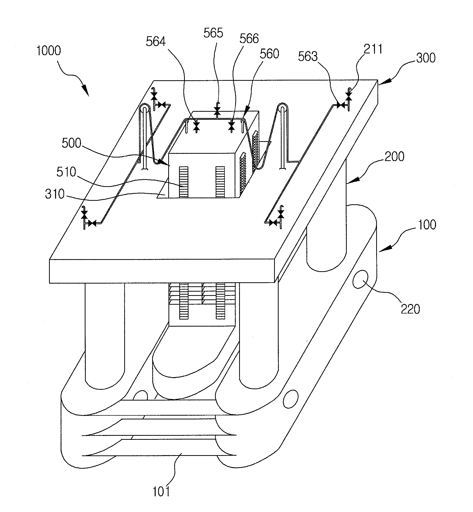
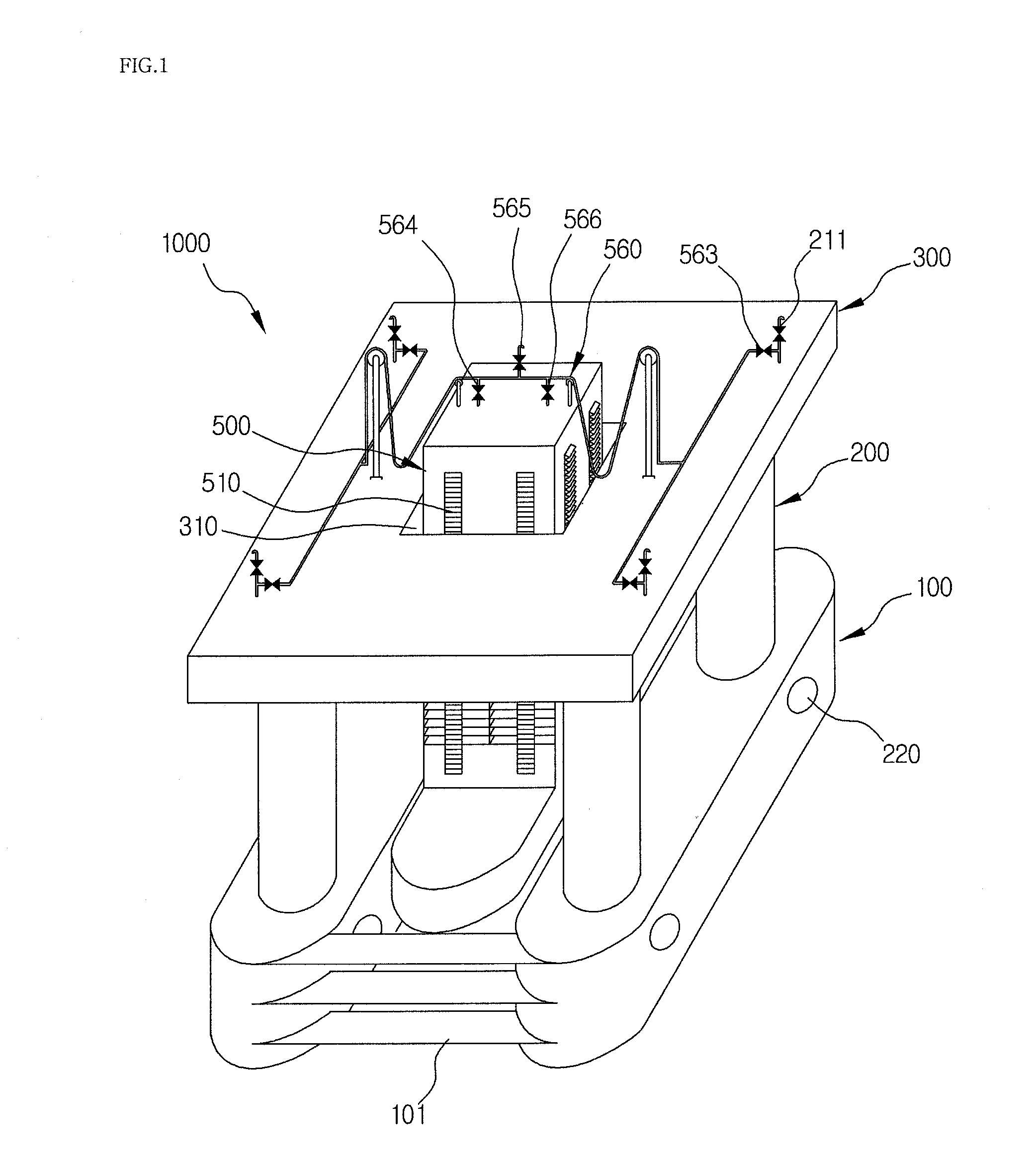
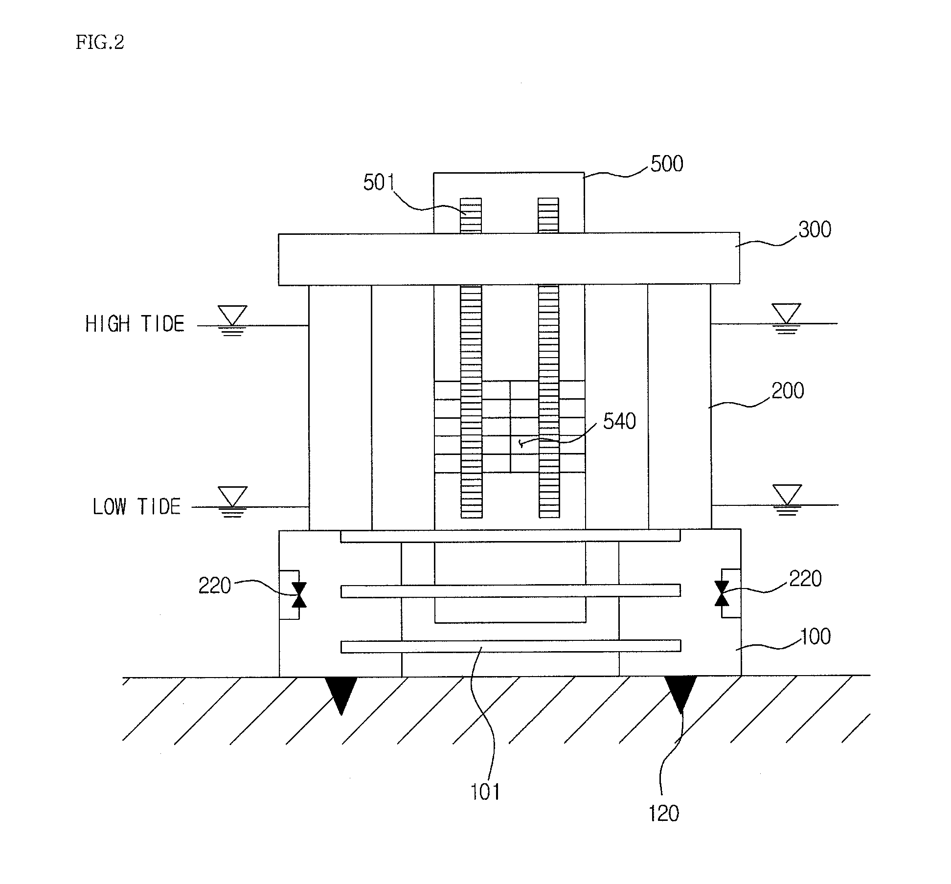
[0031]First, the overall construction of a tidal power generating module 1000 according to an embodiment of the present invention will be described in detail. Generally, the tidal power generating module 1000 may include lower structures 100, compressed air forming tanks 200, an upper structure 300, a vertical movement unit 500, and a power generation unit 400.

Construction and Operation of Lower Structures 100

[0032]The lower structures 100 are a part to support the remaining parts of the tidal power generating module 1000 at the lower side of the tidal power generating module 1000. In this embodiment, a pair of lower structures 100 is provided so that the lower structures 100 are spaced apart from each other by a predetermined distance. The lower structures 100 are connected to each other via connection members 101. An anchor 120 is mounted to the bottom ...


PUM


Abstract

Disclosed herein are a tidal power generating module and a tidal power generating method using the same. The tidal power generating module continuously generates power using compressed air and weight of seawater even at high tide and low tide at which the level of the seawater is not fluctuated in addition to the vertical movement of a vertical movement unit due to the rise and fall of the tide.

Description

BACKGROUND OF THE INVENTION[0001]1. Field of the Invention[0002]The present invention relates to a tidal power generating module and a tidal power generating method using the same, and, more particularly, to a tidal power generating module that is capable of continuously generating power using compressed air and weight of seawater even at high tide and low tide at which the level of the seawater is not fluctuated in addition to the vertical movement of a vertical movement unit due to the rise and fall of the tide and a tidal power generating method using the same.[0003]2. Description of the Related Art[0004]In recent years, various substitute energy sources have attracted considerable attention together with interest in environment as fossil fuel has exhausted. In particular, research has been conducted on methods of using natural energy which does not induce environmental pollution and can be stably obtained.[0005]One of such methods is tidal power generation. A dam is constructed ...

Claims


Application Information

Patent Timeline
Patent Type & Authority Applications(United States)
IPC IPC(8): F03B13/26
CPCY02E10/38F03B13/266Y02E10/30
Inventor JEON, YOUNG HOJEON, YOUNG GYUNKIM, JUNG SUK
Owner KIM JUNG SUK
Why Eureka
Try Eureka