Power generation system

a power generation system and power generation technology, applied in the direction of machines/engines, renewable energy generation, greenhouse gas reduction, etc., can solve the problem that the structure is not applicable to the hydraulic drive system, and achieve the effect of increasing the drive for

Inactive Publication Date: 2015-04-30
CHIU CHENG FU
View PDF5 Cites 3 Cited by
  • Summary
  • Abstract
  • Description
  • Claims
  • Application Information

AI Technical Summary

Benefits of technology

[0007]It is therefore a primary object of the present invention to provide a power generation system, which can collect fluid to increase the drive force. Moreover, the power generation system is applicable to both airflow drive and water flow drive system.

Problems solved by technology

Such structure is inapplicable to hydraulic drive system.

Method used


Image

  • Power generation system
  • Power generation system
  • Power generation system

Examples


Embodiment Construction

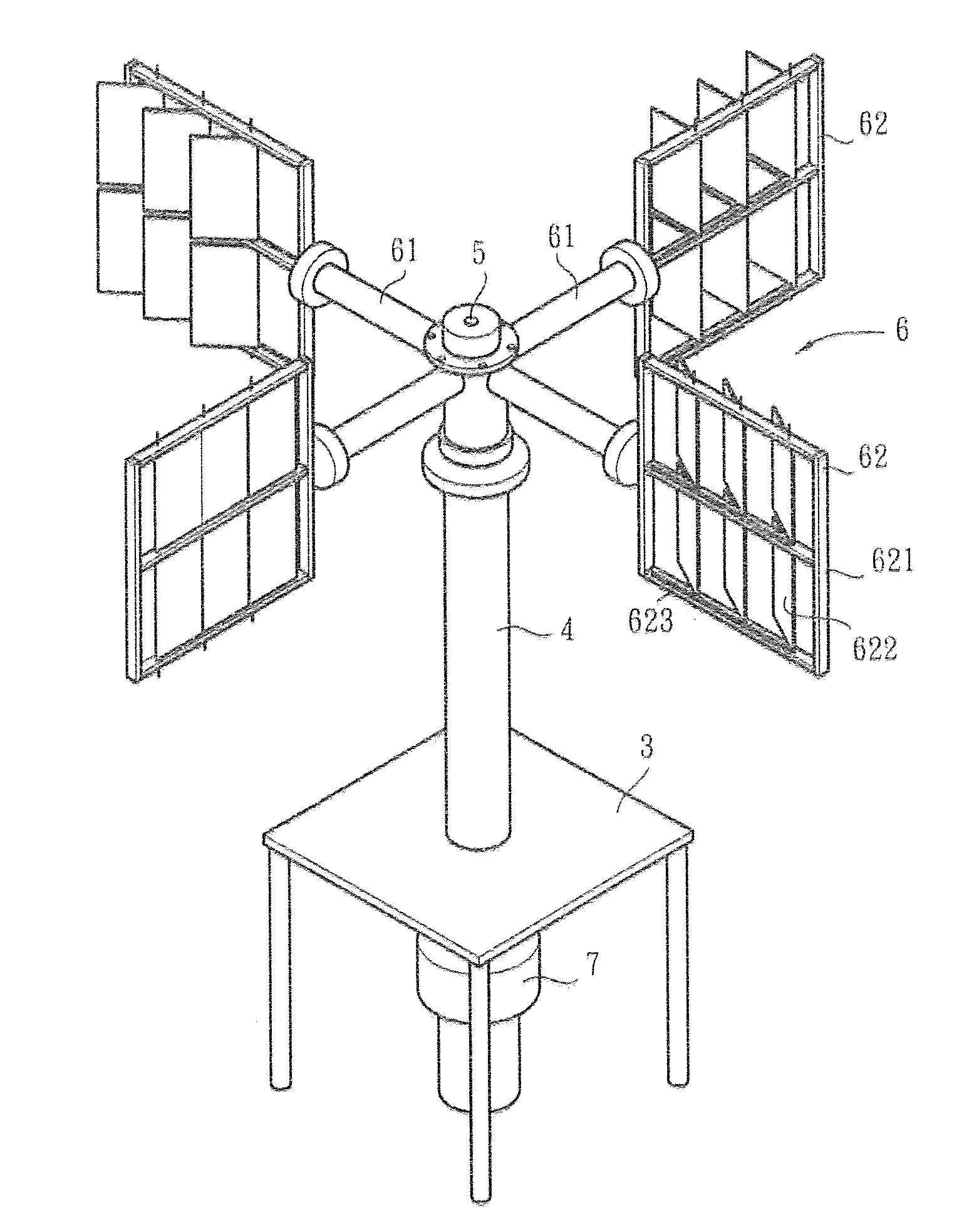
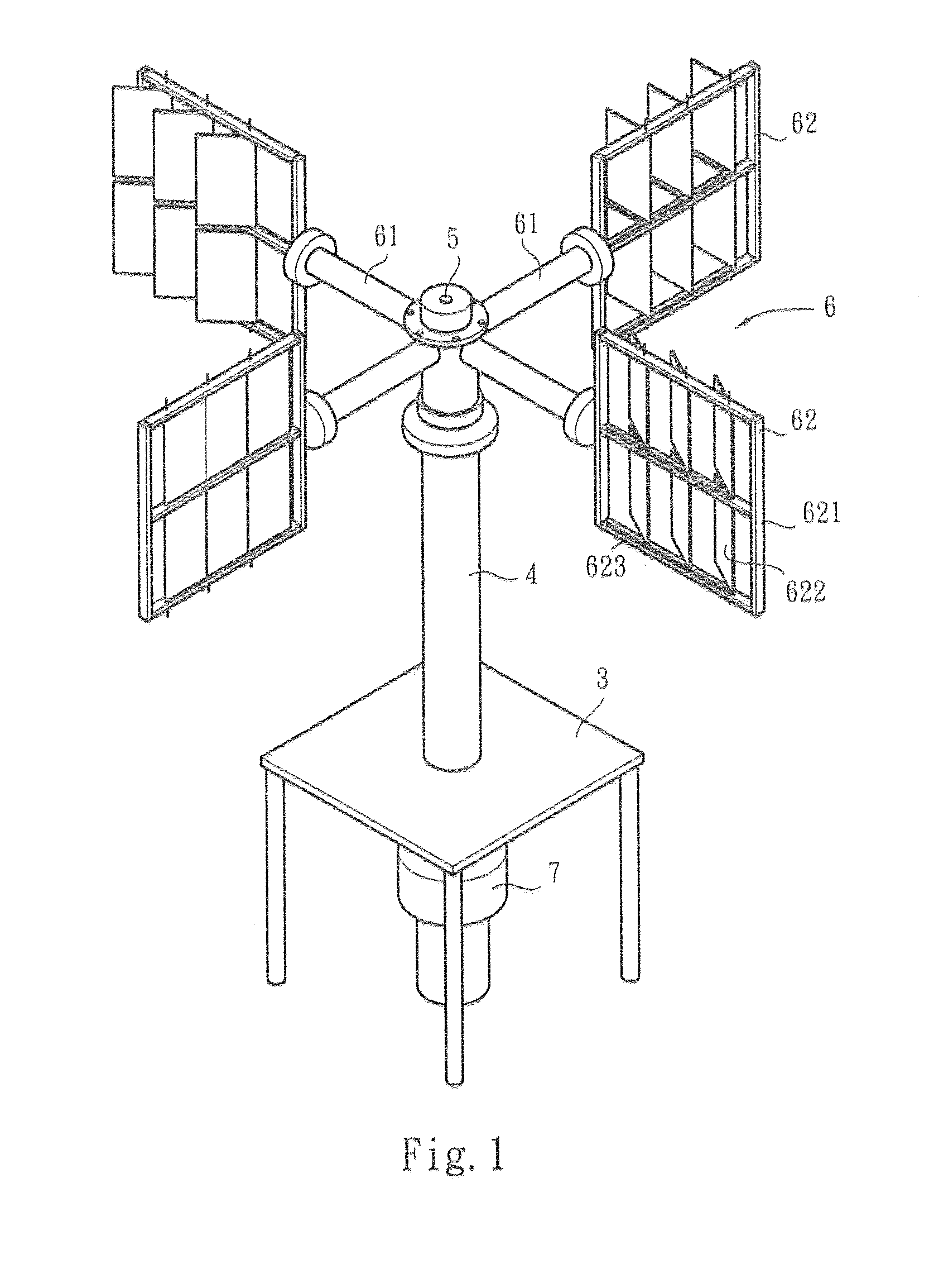
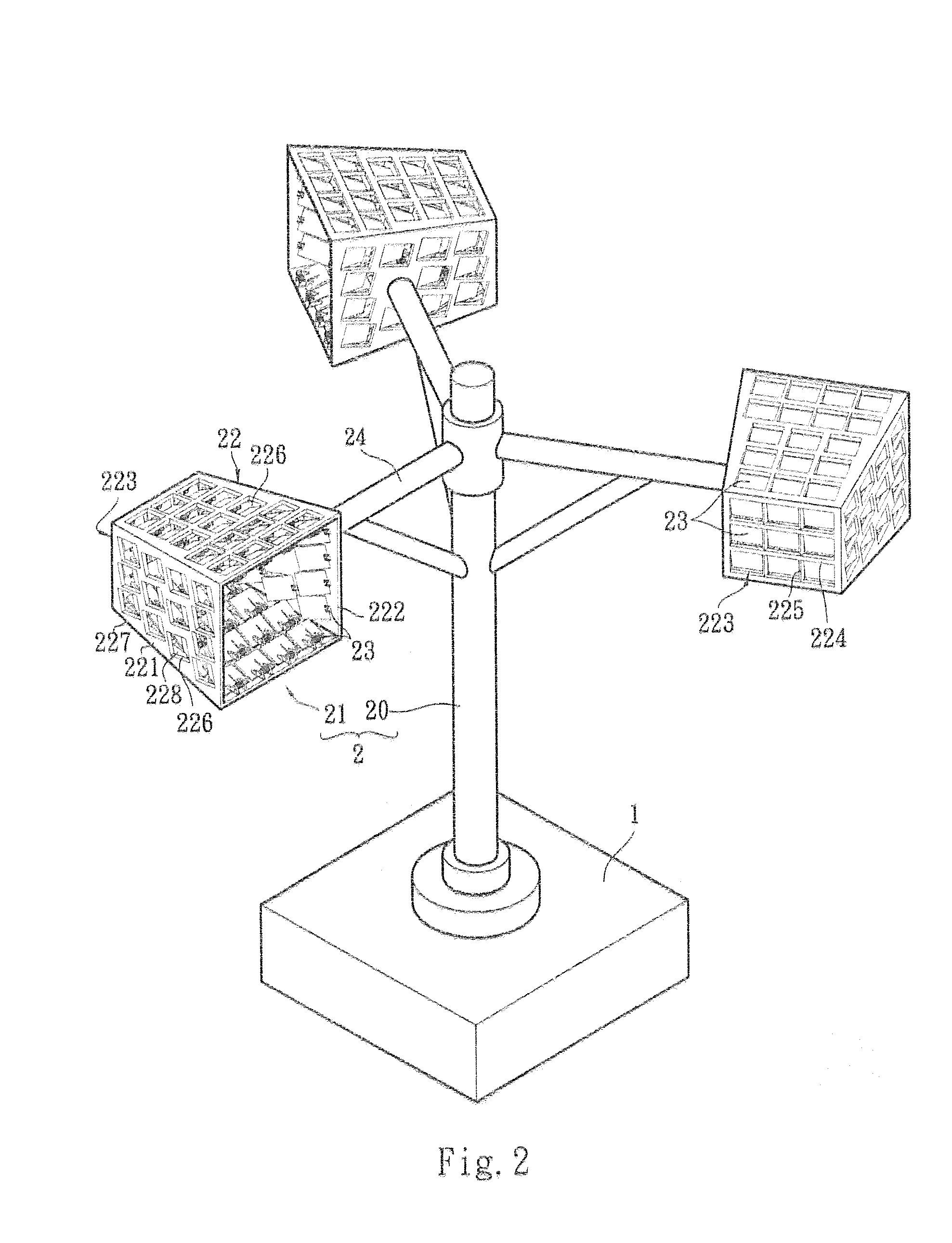
[0027]Please refer to FIGS. 2 to 4. The power generation system of the present invention is applicable to a wind power generation system. The power generation system of the present invention includes a generator 1 and a rotary mechanism 2. The generator 1 serves to convert mechanical energy into electrical energy. The generator 1 pertains to prior art and thus will not be further described. The rotary mechanism 2 serves to generate mechanical energy, including a rotary shaft 20 and at least one drive module 21.

[0028]As shown in FIG. 2, the rotary shaft 20 is rotatably connected to the generator 1. In this embodiment, the generator 1 can be installed on a support lace (not shown) such as the ground. The rotary shaft 20 is upright rotatably disposed on the top section of the generator 1. In this embodiment, there are multiple drive modules 21 connected with the rotary shaft 20 and arranged at intervals. Each drive module 21 has a box-shaped flow collect ion hood 22 and at least one co...


PUM


Abstract

A power generation system includes a generator and a rotary mechanism. The rotary mechanism includes a rotary shaft rotatably connected to the generator and at least one drive module connected with the rotary shaft. The drive module has a flow collection hood. The flow collection hood has a hood body and a flow direction control unit. The hood body defines a front opening and a rear opening and has a peripheral wall positioned between the front and rear openings. The flow direction control unit is disposed on the hood body. The flow direction control unit serves to block and interrupt a fluid flowing from the front opening to the rear opening, while permitting a fluid flowing from the rear opening to the front opening to freely flow through the hood body, whereby the drive module is drivable by the fluid to drive the rotary shaft to one-way rotate.

Description

BACKGROUND OF THE INVENTION [0001]1. Field of the Invention[0002]The present invention relates generally to a power generation system, and more particularly to a power generation system drivable by a fluid to provide mechanical energy and further convert the mechanical energy into electrical energy.[0003]2. Description of the Related Art[0004]In general, a conventional power generation system generates power via a fixed medium. For example, a wind power generator is driven by wind to provide mechanical energy, while a hydraulic power generation system is driven by sea flow or ocean flow to provide mechanical energy and further convert the mechanical energy into electrical energy. Therefore, the power generation systems on the ground and under the sea generally have different drive apparatuses with different structures for providing mechanical energy.[0005]Please refer to FIG. 1. a prior art discloses a wind power drive apparatus. The wind power drive apparatus includes a base 3, a s...

Claims


Application Information

Patent Timeline
Patent Type & Authority Applications(United States)
IPC IPC(8): F03D9/00F03D1/06F03B13/10F03B3/04
CPCF03D9/002F03B13/10F03D1/06F03B3/04F03B17/065F03D3/061F03D3/062F05B2210/16F05B2240/211F05B2240/216Y02E10/20Y02E10/72Y02E10/74
Inventor CHIU, CHENG FU
Owner CHIU CHENG FU
Why Eureka
Try Eureka