Thermo-driven engine

a technology of engine and drive shaft, which is applied in the direction of steam engine plants, gas turbine plants, hot gas positive displacement engine plants, etc., can solve the problems of easy access, pollution of the environment, and exhaust created, and achieve the effect of effectively converting thermal energy into kinetic energy and continuous generation of power

Inactive Publication Date: 2007-08-16
LIN HSING FA
View PDF5 Cites 27 Cited by
  • Summary
  • Abstract
  • Description
  • Claims
  • Application Information

AI Technical Summary

Benefits of technology

[0005] The primary purpose of the present invention is to provide a thermo-driven engine that continuously generates power by effectively converting thermal energy into kinetics to drive a hydraulic motor without loss from heat exchange or lost pressure while promoting a consistent pressure output.
[0012] 1. High efficiency in converting thermal energy into kinetics without heat exchange loss and lost pressure;

Problems solved by technology

Though the combustion of petrol-chemical fuel provides a convenient source to output power, exhaust created in the course of combustion is blamed for polluting the environment while it is prevented from an easy access to the fuel due to the energy crisis in the world.
The consumption of petrol-chemical fuel is not ideal as the source for power output.

Method used


Image

  • Thermo-driven engine
  • Thermo-driven engine
  • Thermo-driven engine

Examples


Embodiment Construction

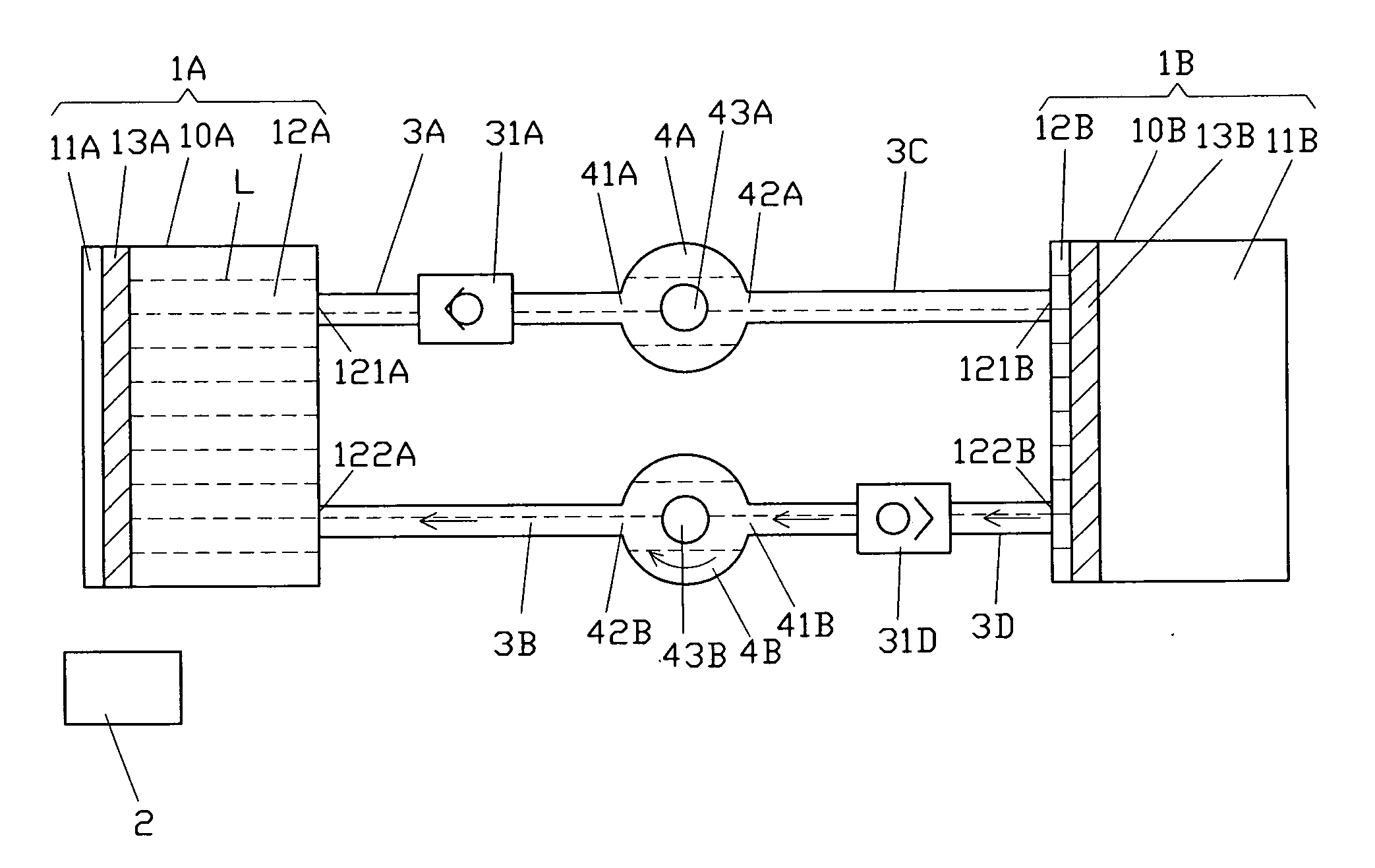
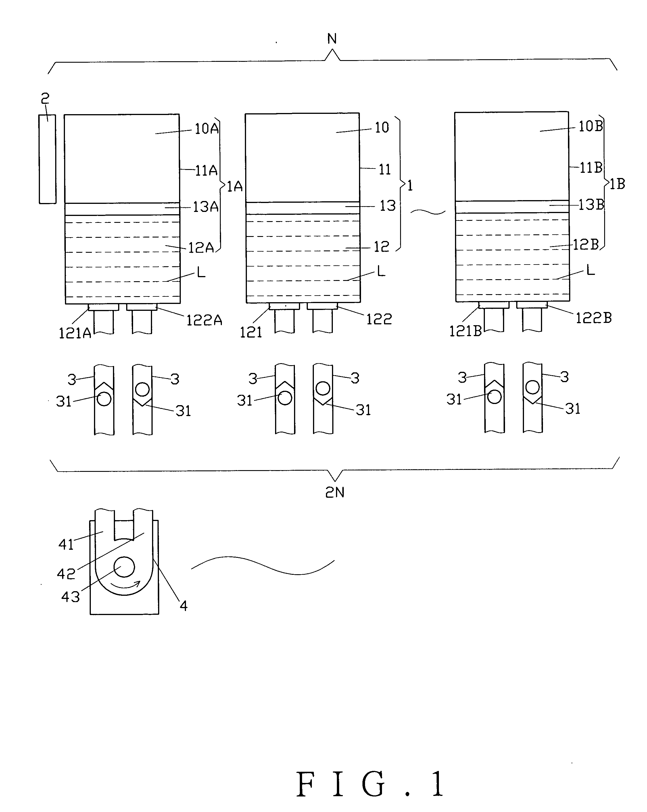
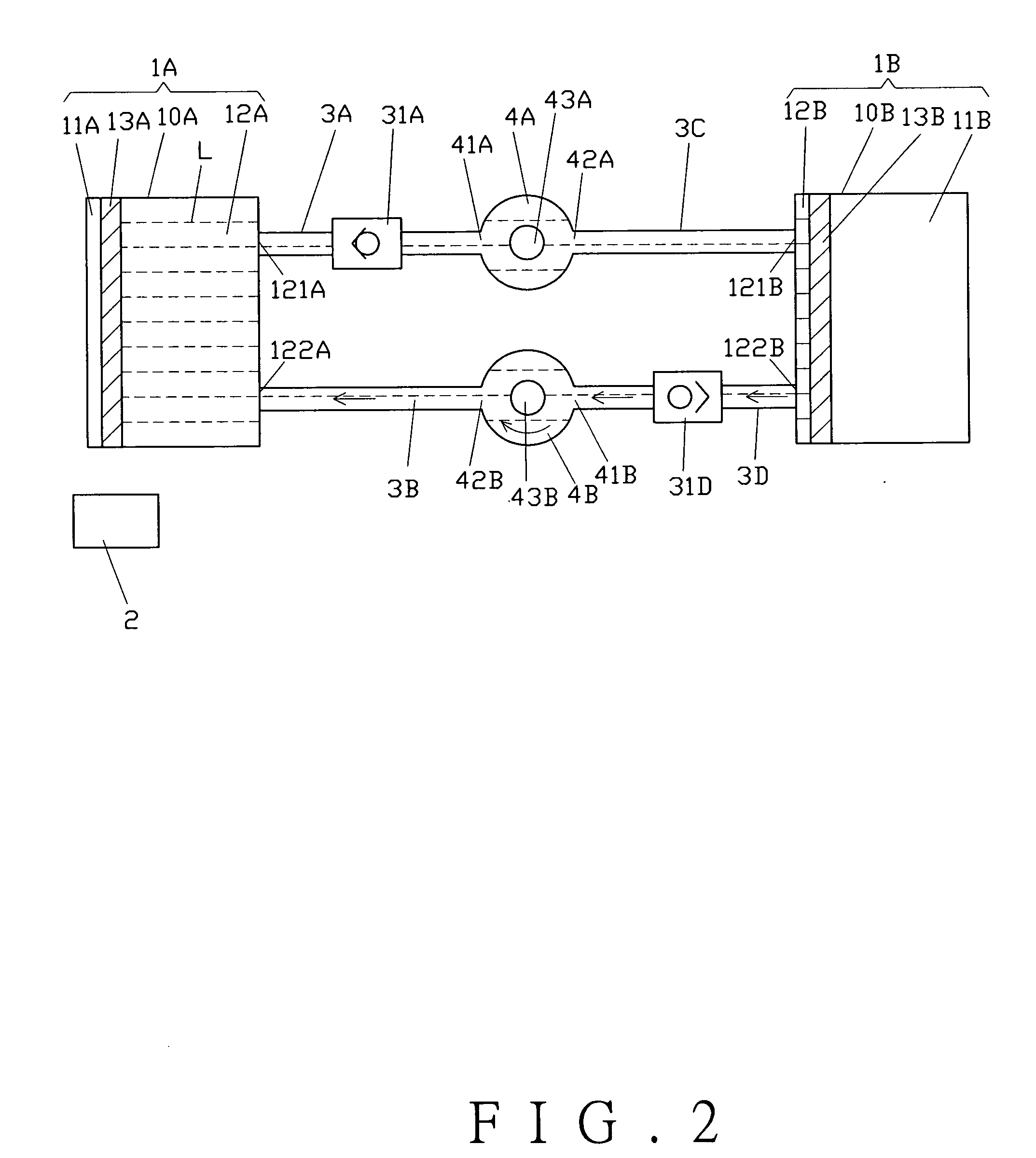
[0021] Referring to FIG. 1, a thermo-driven engine of the present invention comprises N cylinders (1) including a first cylinder (1A) and a last cylinder (1B) wherein N refers to a positive integral and is not less than 2. It is to be noted that all the cylinders including the first cylinder (1A) through the last cylinder (1B) are identical. The cylinder (1) includes a body (10) containing a pair of an air chamber (11) and a hydraulic chamber (12). A piston (13) is disposed between the air chamber (11) and the hydraulic chamber (12). The air chamber (11) contains a gaseous substance (not illustrated). The hydraulic chamber (12) contains a liquid substance (L), and the hydraulic chamber (12) is disposed with an inlet (121) and an outlet (122).

[0022] One or a plurality of heat exchanger (2) is disposed in relation to the air chamber (11) of the cylinder (1), and as illustrated in FIG. 1, an air chamber (11A) of the first chamber (1A) is disposed with the heat exchanger (2).

[0023] 2×...


PUM


Abstract

A thermo-driven engine includes cylinders and at least one hydraulic motor. Each cylinder contains an air chamber and a hydraulic chamber therein. A piston is disposed between both chambers. The air chamber is intermittently heated to create pressure difference in the air chamber of the cylinder to force the piston moving to the hydraulic chamber, thus to drive the hydraulic motor for continuously generating power.

Description

BACKGROUND OF THE INVENTION [0001] (a) Field of the Invention [0002] The present invention relates to a thermo-driven engine, and more particularly, to one that has air chambers of cylinders intermittently heated for the air therein to create pressure difference to force pistons to move to hydraulic chambers thus to compress hydraulic liquid to drive a hydraulic motor for continuously generating power for utilization. [0003] (b) Description of the Prior Art [0004] Whereas there are many power sources available in the market, most of them operate by combusting petrol-chemical fuels including gasoline and diesel. An automobile or motorcycle is driven by power generated by combusting gasoline in the engine. Though the combustion of petrol-chemical fuel provides a convenient source to output power, exhaust created in the course of combustion is blamed for polluting the environment while it is prevented from an easy access to the fuel due to the energy crisis in the world. The consumptio...

Claims


Application Information

Patent Timeline
Patent Type & Authority Applications(United States)
IPC IPC(8): F01B29/08F01K25/02F01K25/00F02C1/04F02G1/00
CPCF01K15/02F02G1/044F01K25/02
Inventor LIN, HSING-FA
Owner LIN HSING FA
Why Eureka
Try Eureka