
Gauge for aligning hair trimmer blades

a technology for aligning blades and hair trimmers, which is applied in the direction of drilling/boring measurement devices, manufacturing tools, instruments, etc., can solve the problem that the blades often tend to shift out of alignmen

Inactive Publication Date: 2012-08-09
TONALAN RUSSELL +1
View PDF9 Cites 13 Cited by
  • Summary
  • Abstract
  • Description
  • Claims
  • Application Information

AI Technical Summary

Problems solved by technology

Its limitations are that the blade set is laid onto the gauge and when the adjustment screws are tightened, the blades often tend to shift out of alignment.

Method used


Image

  • Gauge for aligning hair trimmer blades
  • Gauge for aligning hair trimmer blades
  • Gauge for aligning hair trimmer blades

Examples


first embodiment

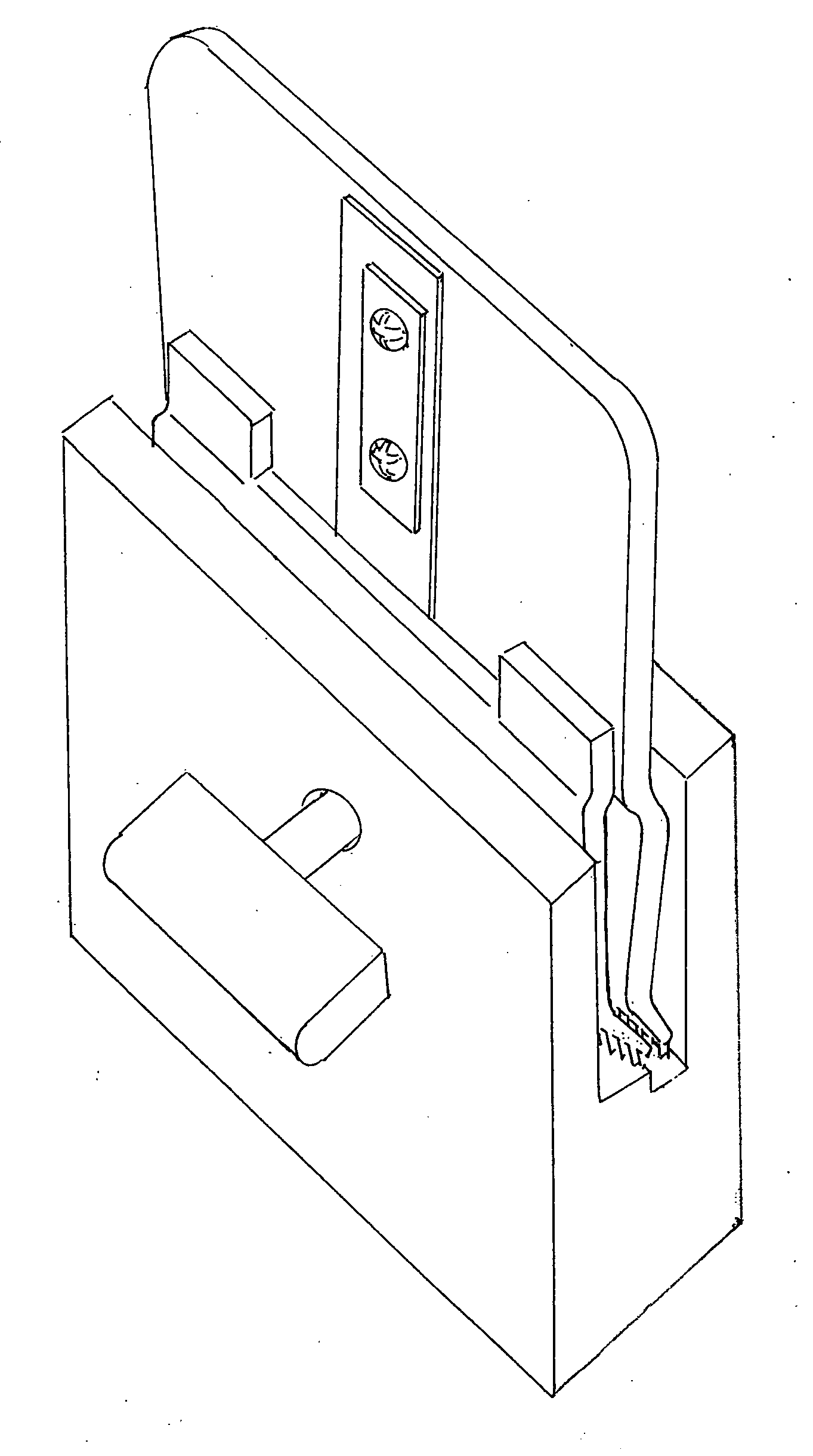
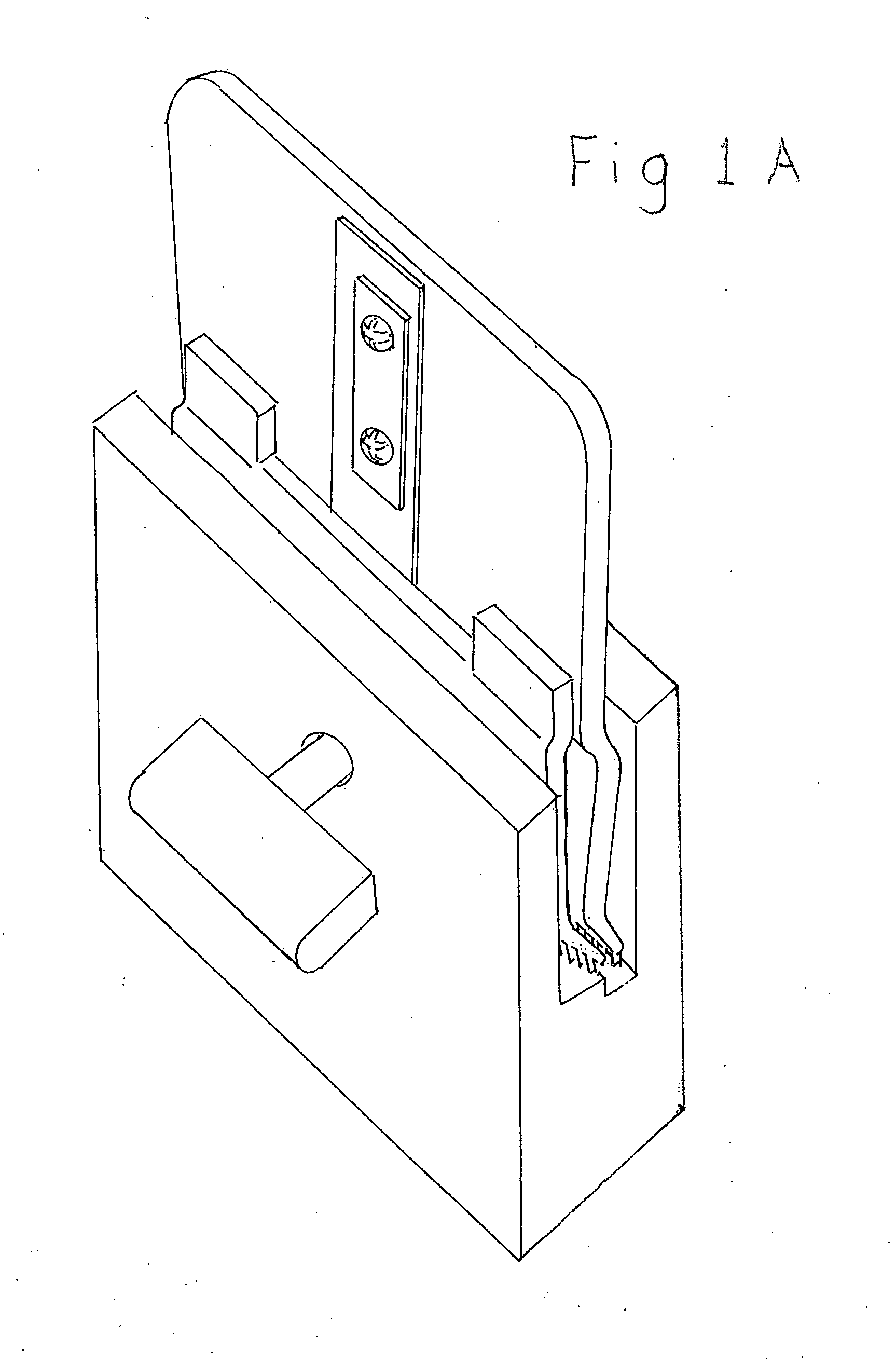
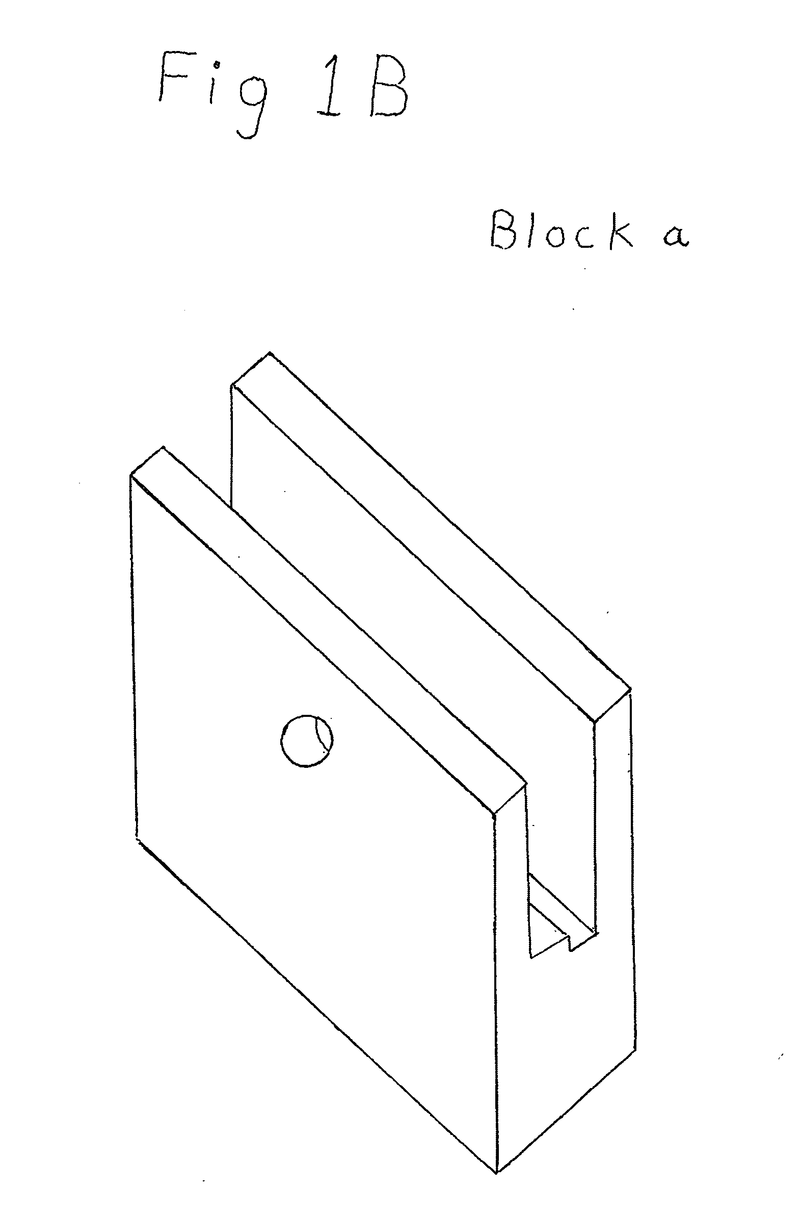
[0019]One embodiment FIG. 1B shows the gauge block (a) with stepped slot. The front of the said gauge block has a hole to be used as a pivot point for the pin (b). FIG. 1C shows the said pin (b). This said pin's diameter is slightly smaller than the hole in said gauge block (b).

DETAILED DESCRIPTION-FIGS. 2B AND 2C

second embodiment

[0020]The second embodiment FIG. 2B shows gauge block (c) with stepped slot. The front of the said gauge block (c) has a clearance cutaway for the style of blade set to be adjusted. FIG. 2C shows a spring clip (d). This attaches to the front piece of the set of blades and swings under the bottom of the said gauge block (c) and clips under it.

Operation

[0021]The user removes the blades that are to be adjusted from the vibratory trimmer and then loosens the alignment screws slightly. The user then installs the set of blades into the slot of the blade setter gauge.

First Embodiment-FIGS. 1C, 1D, 1E

[0022]The user places the pin (b) FIG. 1C into the hole in the front of the blade setter gauge block (a), making sure that the hole in the movable blade is behind the hole in the blade setter gauge block (a) FIG. 1E. The blade setter gauge block (a) with the blades and pin (b) inserted can be in one hand as shown: FIG. 1D. The pin (b) is being pushed upward with the thumb FIG. 1E. The fact tha...


PUM


Abstract

A gauge for setting the trimmer blades of a vibratory hair trimmer comprising of a gauge block with a slot in it of the shape of a perfectly adjusted set of trimmer blades.One embodiment, the gauge block has a hole in the front that would line up with hole in the front of the trimmer blade set. A pin with a diameter slightly smaller is inserted into the hole and pushed up with the thumb. The pin cantilevers on the edge of the hole and forces the front blade down into the slot. The back blade is forced down with the forefinger as the adjustment screws are tightened.Another embodiment has a spring clipped to the front of the front blade of the blade set and forces it into the groove when the adjustment screws are tightened.

Description

[0001]This application claims the benefit of provisional patent application Ser. No. 61 / 274,035, Confirmation No. 4783, filed 2009 Aug. 12 by the present inventors.[0002]This invention, the blade setter, is a gauge to set the distance and parallelism between the stationary blade and the movable blade of a vibratory hair trimmer.BACKGROUNDPrior Art[0003]Wahl Clipper Corporation blade adjustment fixture see pages A & B.[0004]Barbers have to reset the blades of a vibratory trimmer by eye when the blades move out of alignment from use.[0005]The only other gauge known is made by a company for a specific blade marketed by its own company. Its limitations are that the blade set is laid onto the gauge and when the adjustment screws are tightened, the blades often tend to shift out of alignment.SUMMARY[0006]The blade setter is a block with a slot with a stepped groove at the base of the slot. The set of blades are restricted from movement out of adjustment by the shape of the groove and (emb...

Claims


Application Information

Patent Timeline
Patent Type & Authority Applications(United States)
IPC IPC(8): G01B1/00
CPCB26B19/3846B26B19/3893
Inventor TONGES, ALAN RUSSELLBEAUJOUR, ALEX BANARD
Owner TONALAN RUSSELL
Learn More