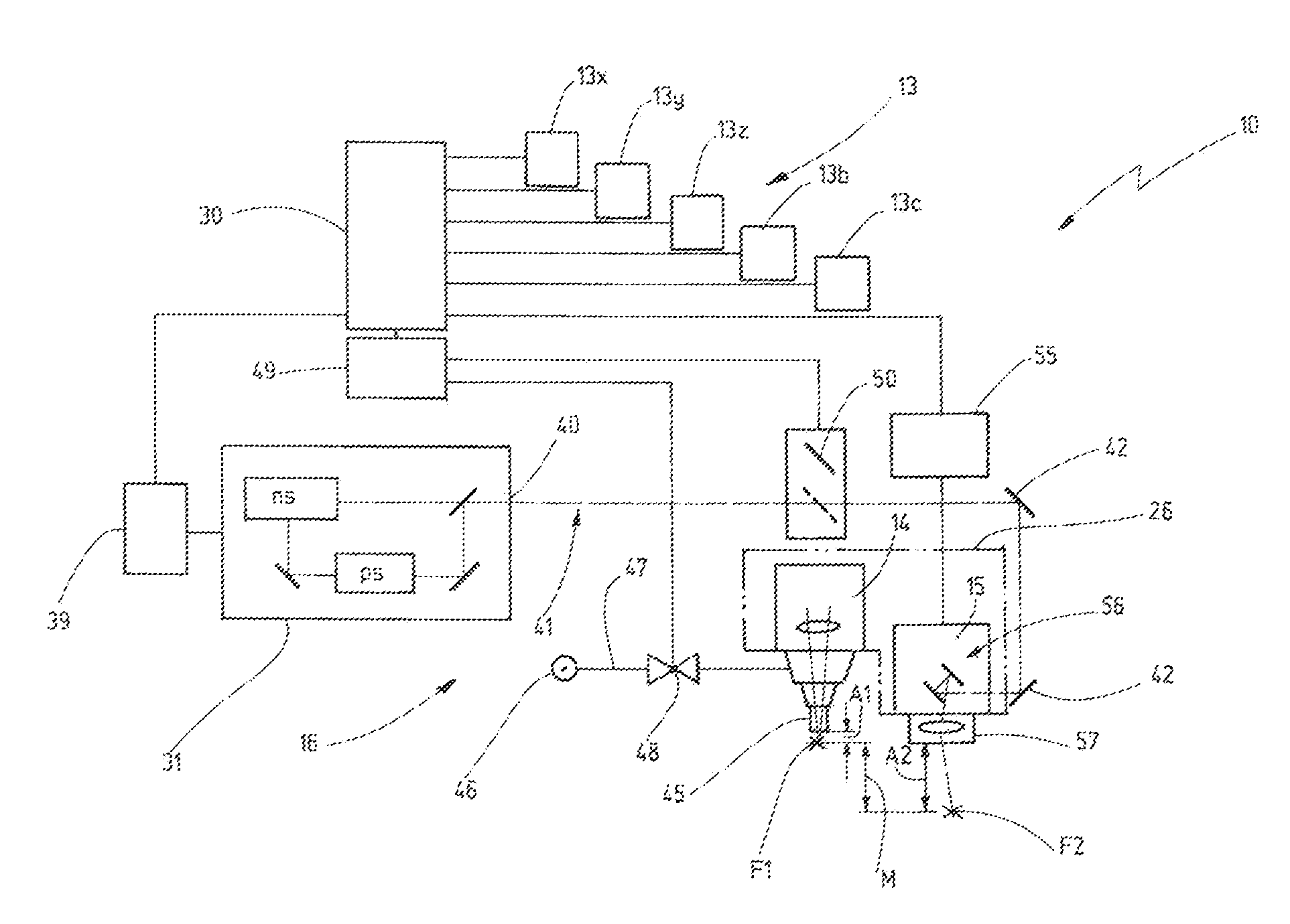
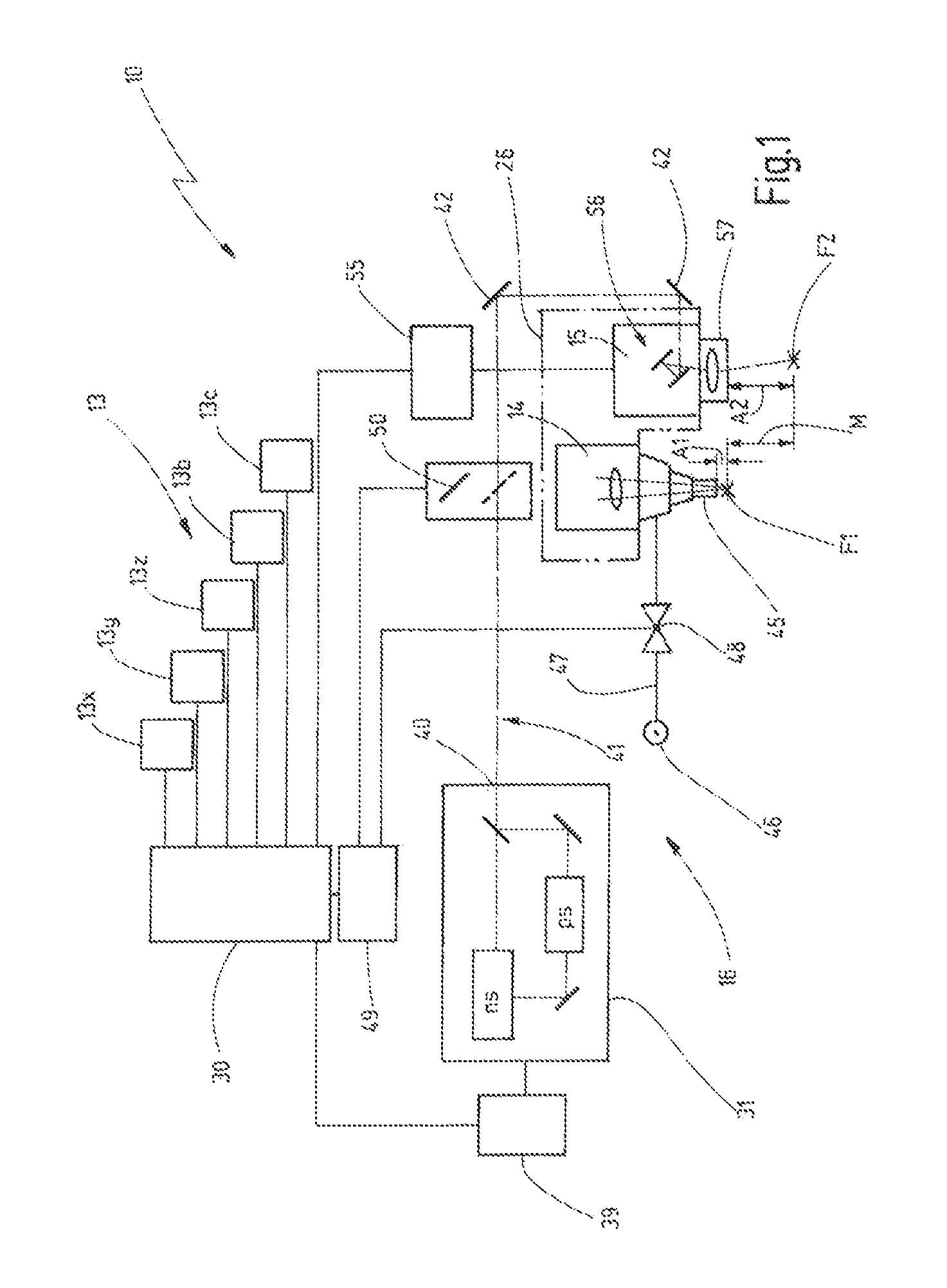
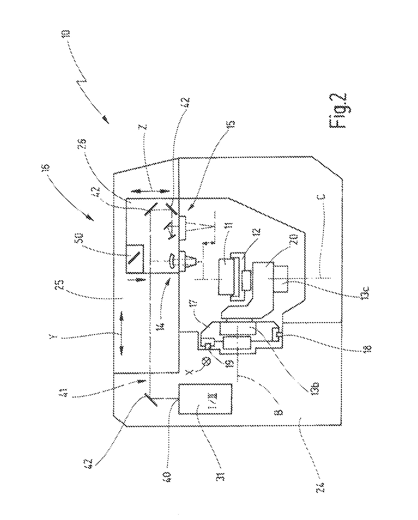
[0007]The invention provides a laser machining apparatus (10), as well as a method for machining a workpiece (11). A rotating
cutting tool having a cutting edge (62) and a flank (64) is manufactured from the workpiece (11). The laser machining apparatus (10) works in two different operating
modes. In the first operating mode, a first laser head (14) is used for machining the workpiece (11) at high advance speeds of the workpiece (11) relative to the first laser head (14). In doing so, the workpiece (11) is
cut by laser melt cutting so as to display a rough desired contour. In the first operating mode, the duration of the laser pulses is in the
nanosecond range. Subsequently, the laser machining apparatus (10) is operated in the second operating mode. In doing so, the laser pulses are generated with a
pulse duration in the
picosecond range, said laser pulses exhibiting a smaller mean power than those in the first operating mode. In the second operating mode, a second laser head (15) in the form of a
scanner head is activated by means of an optical
scanner system (56). This optical scanner
system directs the laser pulses onto a two-dimensional pulse area (65) on the surface of the workpiece (11). Different from the first operating mode I, the
material removal is accomplished by
laser ablation in the second operating mode. The thermally influenced zone formed in the first operating mode due to the thermal action of the laser pulses on the workpiece (11) is at least partially removed again by
laser ablation during the subsequent machining step, so that a high quality of the machined workpiece (11) is achieved.
[0010]Indeed, high machining speeds are achieved in the first operating mode; however, due to the thermal action of the laser on the workpiece, a thermally affected zone is produced on the workpiece, said zone having a negative effect on the properties of the cutting tool that is to be produced, for example. Therefore, in the second operating mode, the laser arrangement machines the workpiece by laser
ablation. The material is converted into a
plasma cloud by ultra-short laser pulses, in which case the duration of the action of the laser pulses is so minimal that no thermally affected zone will form. In this case, the duration of action of the laser pulse on the workpiece is not adequate for this. During this second operating mode, preferably at least one part and, in particular, the entire thermally affected zone that has formed in the first operating mode is removed again. The thermally affected zone is removed at least in the regions of the workpiece where high quality is required such as, for example, in the regions of the cutting edge of a cutting tool. In both operating
modes, the workpiece is machined at the same point of the outside contour in order to produce the desired three-dimensional form. Due to the two-
step method, the workpiece mounted in the holding means can be machined very economically. In this manner, it is possible to thus manufacture cutting tools in a particularly efficient manner. In addition, high-quality workpiece machining is ensured.
[0012]It is advantageous when the first focus region in which the laser pulses emitted by the first laser head can be focused, does not have spatial intersections with the second focus region in which the laser pulses emitted by the second laser head can be focused. In particular, the first focus region of the first laser head is arranged along its
optical axis at a first working distance from the first laser head. The second focus region is located at a second working distance from the second laser head. In a preferred embodiment, the second working distance is greater than the first working distance. This offers the
advantage that, while the workpiece is being machined in the second operating mode, spatial moving and / or positioning of the workpiece relative to the second laser head are possible without impairment by the first laser head. As a rule, the finishing pass of the workpiece in the second operating mode requires a more complex alignment and movement of the workpiece relative to the second laser head with the use of the infeed axes than is the case in the first operating mode in the course of rough-cutting. If the second working distance is selected greater than the first working distance, a sufficiently large
free space is available for tool movement.

