Fiber optic end face inspection probe and system

a fiber optic end face and probe technology, applied in the direction of testing fibre optic/optical waveguide devices, instrumentation, structural/machine measurement, etc., can solve the problems of equipment damage, significant back reflection, significant number of fiber optic system failures, etc., and achieve the effect of easy operation and quick and easy use of a single hand

Active Publication Date: 2011-04-14
LEVIN PIOTR ANATOLIJ +3
View PDF4 Cites 40 Cited by
  • Summary
  • Abstract
  • Description
  • Claims
  • Application Information

AI Technical Summary

Benefits of technology

It is another aspect of the present invention to provide a fiber optic end face inspection probe that operates quickly and easily using a single hand.

Problems solved by technology

Contamination of fiber optic end faces is the cause of a significant number of fiber optic system failures.
A single contaminant particle on the end face of an optical fiber can cause significant back reflection, insertion loss, and equipment damage.
Although capable of performing the necessary task, conventional video inspection probes have significant disadvantages.
The ergonomics of using the video inspection probe, for example, are neither efficient nor safe.
When the connector housing the fiber optic end face to be inspected is positioned such that its inspection requires use of a ladder, or is otherwise difficult to reach, the user may be put into an awkward and / or unsafe position.
He may be able to hold it in the same hand that is securing his position, but this could jeopardize his grip, and, therefore, his safety.
Should the tether be too short, he may have to position himself awkwardly and unsafely to reduce the distance between the two devices.
Alternatively, he may have to stretch the tether, risking damage to the devices and the possibility that the surprise of a break would unseat him.
Should the tether be too long, he risks entangling himself, the devices, and other objects around him, again posing a risk to his safety.
In summary, the need to juggle both the handheld viewing device and the inspection probe, tethered together, and to ensure his own safety, present a risk to the user's safety as well as a risk of damage to the inspection probe, the handheld viewing device, or both, which would require costly repairs or replacement.
These systems also require that the data be analyzed on the small screen of the handheld viewing device; a device which may have limited functionality beyond basic viewing and analysis capabilities.
In addition, the total portable video inspection probe system, including the inspection probe with video capabilities and the handheld viewing device with viewing screen, requires significant battery power that needs frequent recharging.
As a result, the user continuously shakes the probe, which makes the focusing task difficult to perform and greatly increases the time that it takes to check the fiber optic end face within each connector.
However, this option has not been implemented for a number of reasons.
First, video streaming via wireless transmission is limited by the speed at which the screen may be refreshed.
Thus, images are often blurry and the operator may have difficulty determining exactly when the video probe has been correctly placed and is focused.
Moreover, the power necessary to continuously transmit video wirelessly would be significant, requiring a bulky battery and / or frequent battery charging.

Method used


Image

  • Fiber optic end face inspection probe and system
  • Fiber optic end face inspection probe and system
  • Fiber optic end face inspection probe and system

Examples


Embodiment Construction

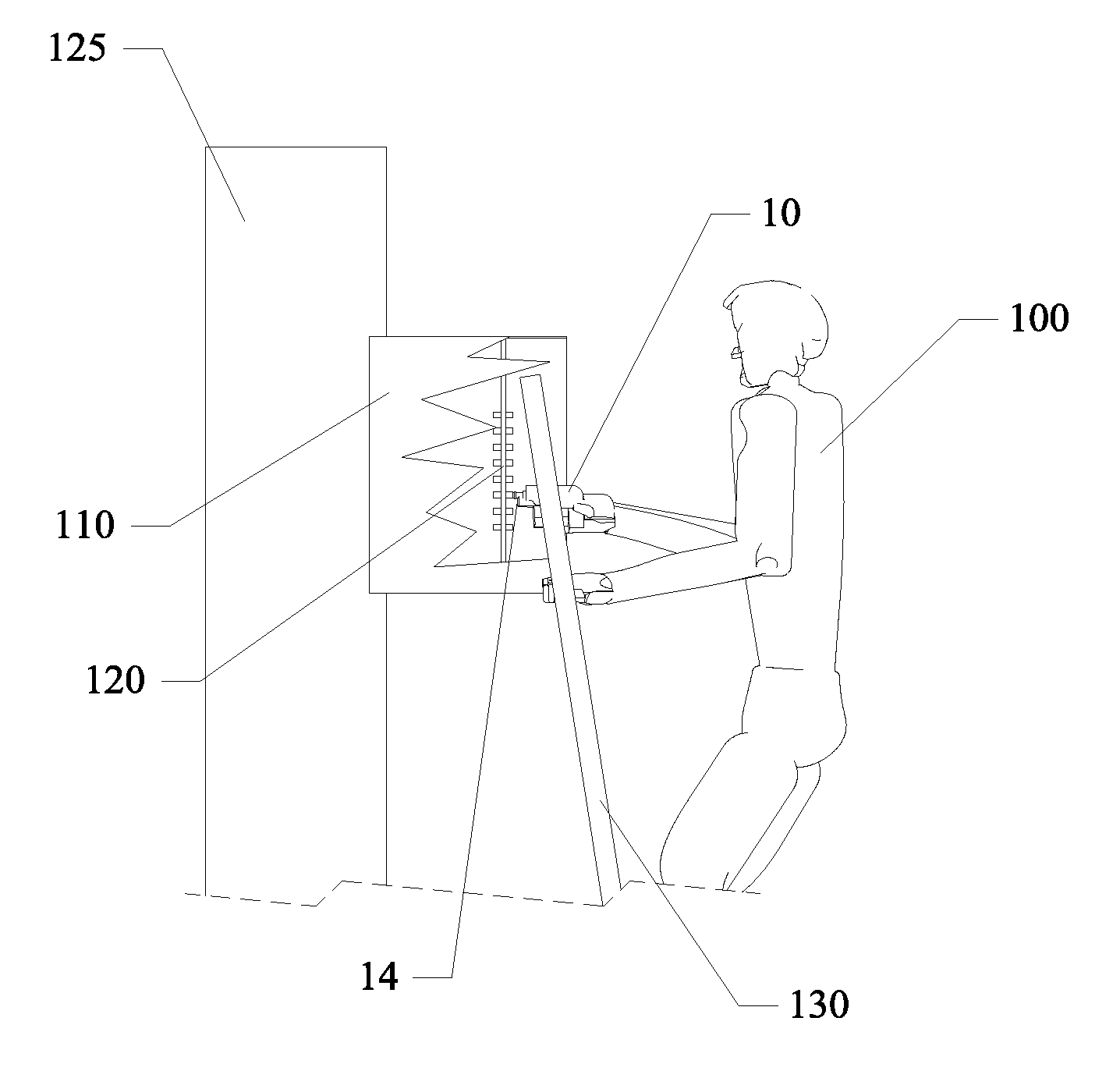
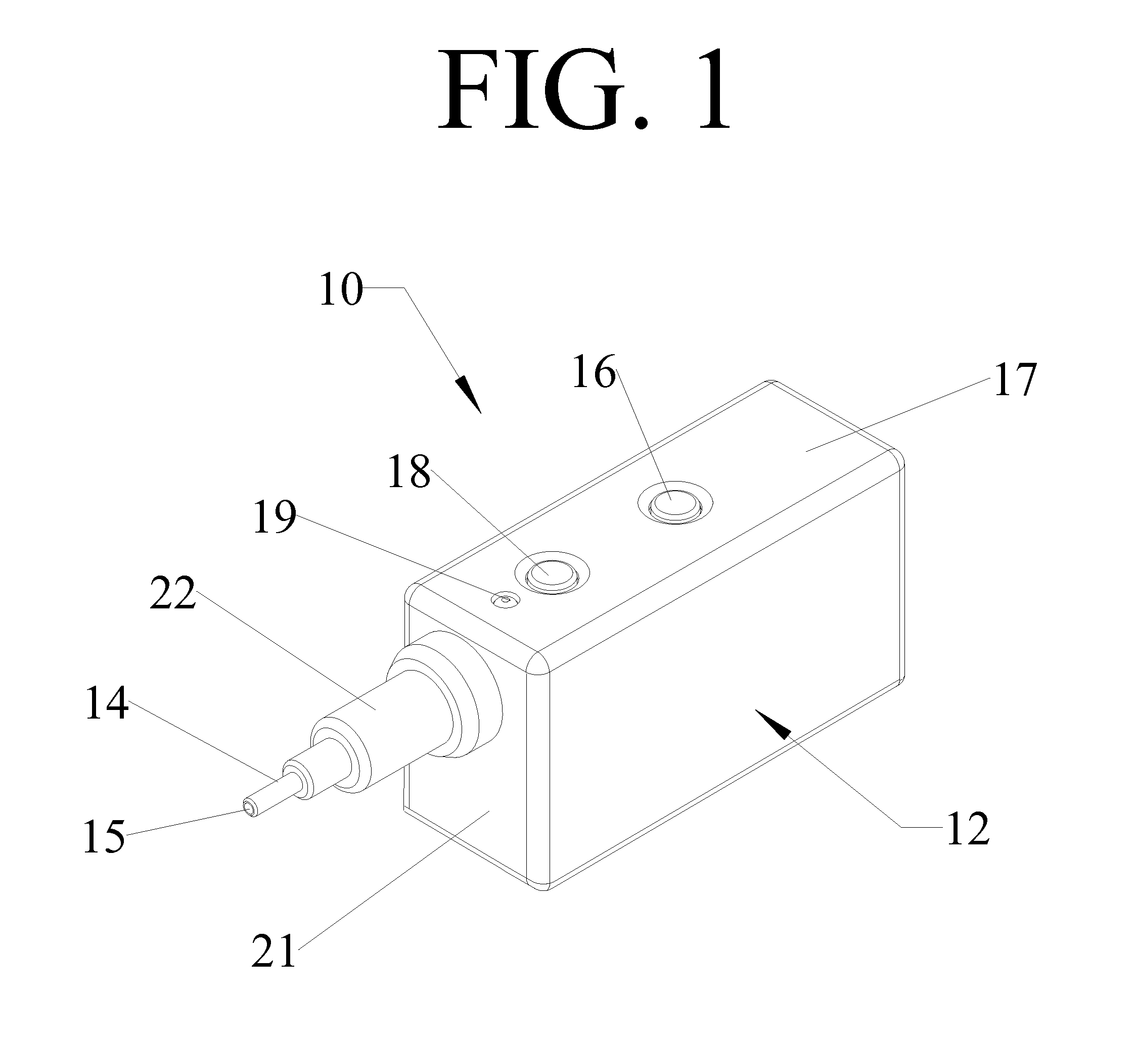
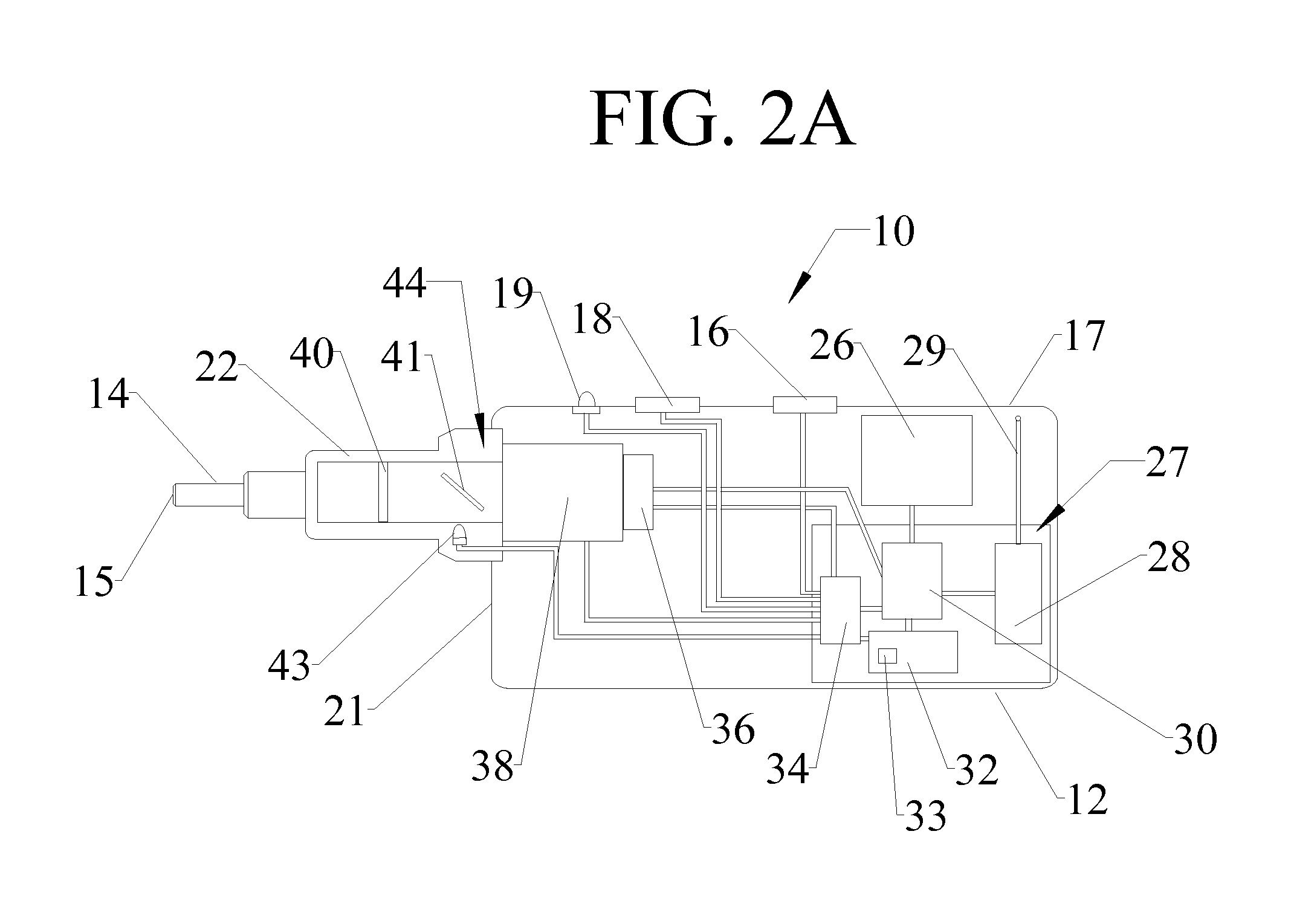
The fiber optic end face inspection probe of the present invention includes many of the same features as those commonly used in the art of fiber optic end face inspection probes. Examples of such fiber optic end face inspection probes include the JDSU FBP-P1 Video Inspection Probe, the AFL Telecommunications Noyes® VFS2 View Safe Video Microscope, and the EXFO FIP-400 Fiber Inspection Probe. These fiber optic end face inspection probes are handheld devices that may be applied to a fiber optic end face to be inspected for imperfections. The principal difference between the fiber optic end face inspection probe of the present invention and fiber optic end face inspection probes commonly used in the art is that prior art probes use video, which must be manually focused to assess the condition of the fiber optic end face. Further, because of the power requirements inherent in video based devices, these probes have heretofore been tethered to a separate viewing device that houses a large...


PUM

PropertyMeasurementUnit
insertion lossaaaaaaaaaa
timeaaaaaaaaaa
distanceaaaaaaaaaa

Abstract

A fiber optic end face inspection probe that includes a power control, an image control; a probe adaptor and probe end extending from a housing; an electronics module that includes a microprocessor, a memory and an optional wireless transmitter; and an autofocus camera system that includes a lens, a motor adapted to move the lens in order to focus the image through the lens, and an image sensor that is adapted to accept the image passing through the lens and transmit this image to the electronics module.

Description

FIELD OF THE INVENTIONThe present invention relates to systems for inspecting fiber optic end faces, and in particular to an improved handheld probe for fiber optic connector end face inspection.BACKGROUND OF THE INVENTIONThe present invention pertains to the inspection of the end faces of optical fibers. Contamination of fiber optic end faces is the cause of a significant number of fiber optic system failures. A single contaminant particle on the end face of an optical fiber can cause significant back reflection, insertion loss, and equipment damage. Visual fiber optic end face inspection is the only way to determine if the end faces of optical fibers are clean, and is essential to reliable functionality.There are many products in the art of visual fiber optic end face inspection. Most of these products are video inspection probes that include an inspection probe connected to a handheld viewing device via a cable. The inspection probe captures video of the fiber optic connector end...

Claims


Application Information

Patent Timeline
Patent Type & Authority Applications(United States)
IPC IPC(8): G01N21/00
CPCG01M11/3154G01M11/30G01M11/088
Inventor LEVIN, PIOTR ANATOLIJDOLZNIKOVAS, IGORISKAVALIAUSKIS, VALDASKUSTOV, MICHAIL
Owner LEVIN PIOTR ANATOLIJ
Why Eureka
Try Eureka