Driving light emitting diodes

a technology of light-emitting diodes and driving lights, which is applied in the direction of electric variable regulation, process and machine control, instruments, etc., to achieve the effect of reducing the number of main power supplies

Active Publication Date: 2010-04-29
SIGNIFY HLDG BV
View PDF13 Cites 43 Cited by
  • Summary
  • Abstract
  • Description
  • Claims
  • Application Information

AI Technical Summary

Benefits of technology

[0003]It is an object of the invention to minimize the number of main power supplies required for driving the differently colored LED's while still being able to adjust the spectral composition of the resultant mixed light.
[0008]In an embodiment, the main power supply comprises or is a SMPS. Consequently, the majority of the current through the LED's is generated with high efficiency. The disadvantages of such a SMPS, which is bulky, expensive, slow and has ripple on the output voltage, are mitigated by the secondary power supplies. The secondary power supplies, which may be linear power supplies, need to supply a relatively small power, can be cheap, fast and can compensate for the ripple of the SMPS.
[0010]In an embodiment, the secondary power supply comprises a controllable linear power supply. Because the current supplied or drawn by the secondary power supply is much smaller than the current supplied by the first power supply, the low efficiency of the linear power supply is not a problem. The use of a linear power supply has the advantage that a fast and well defined variation of the current supplied is possible. Further, the ripple of a linear power supply is much lower than that of an SMPS. Thus, the use of the linear power supply has the advantage that the control of the spectral composition, which is predominantly determined by the difference of the currents through different colored LED's, can be controlled very accurately.

Problems solved by technology

It is a disadvantage of the prior art apparatus that three SMPS's are required to be able to drive the differently colored LED strings such that their color point can be controlled.

Method used


Image

  • Driving light emitting diodes
  • Driving light emitting diodes
  • Driving light emitting diodes

Examples


Embodiment Construction

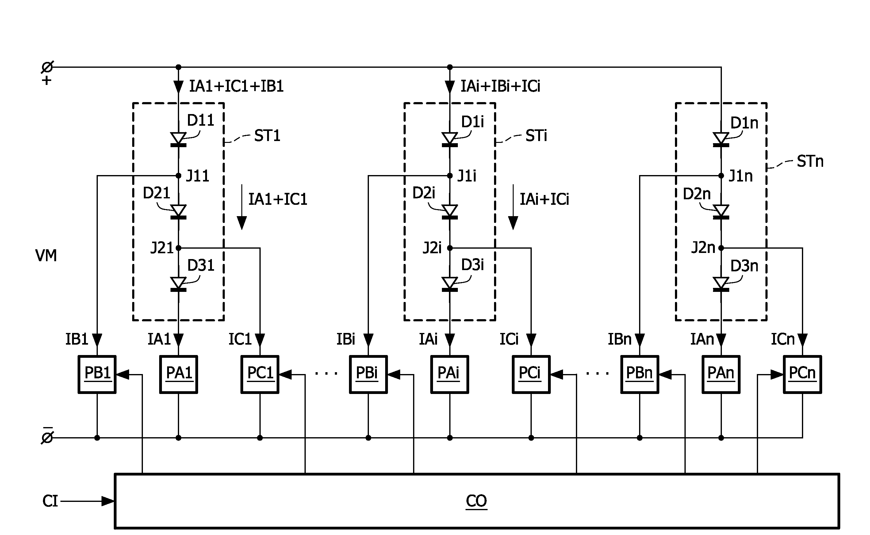
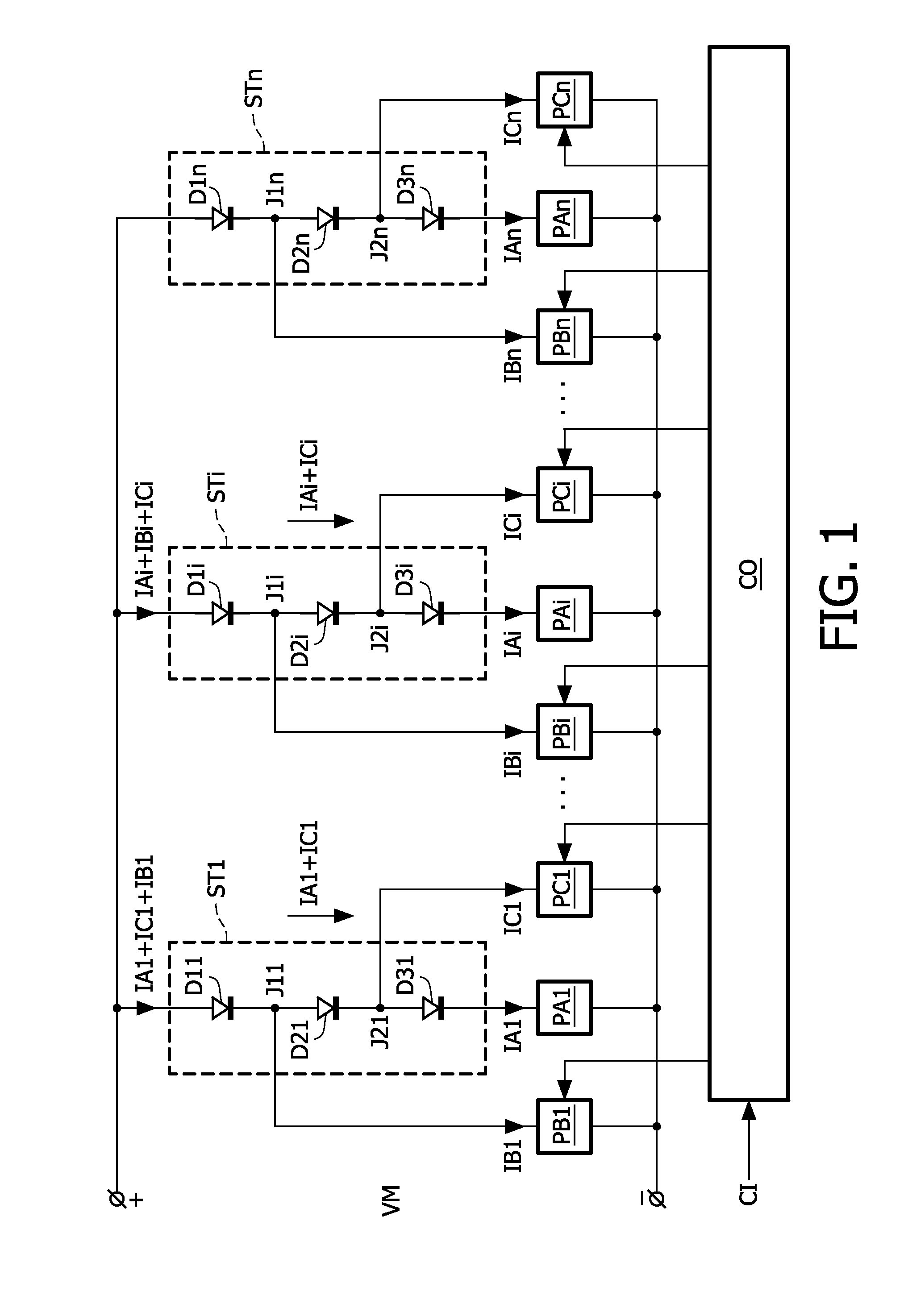
[0021]FIG. 1 schematically shows a block diagram of a backlight unit which comprises a plurality of strings of LED's and a plurality of power supplies driving the strings. Each of the n strings STi comprises, by way of example, three differently colored LED's D1i, D2i, D3i. The first string ST1 comprises a series arrangement of the three LED's D11, D12, D13, the ith string STi comprises a series arrangement of the three LED's D1i, D2i, D3i, and the nth string STn comprises a series arrangement of the three LED's D1n, D2n, D3n. In the now following the indices 1 to n are used to indicate a particular one of the n items. However, the index i is also used to indicate the item in general. Thus: “the LED's D1i” means the LED's D11 to D1n in general, or said differently, “the LED D1i” means an arbitrary one of the LED's D11 to D1n, and “the LED D11” means the particular LED D11.

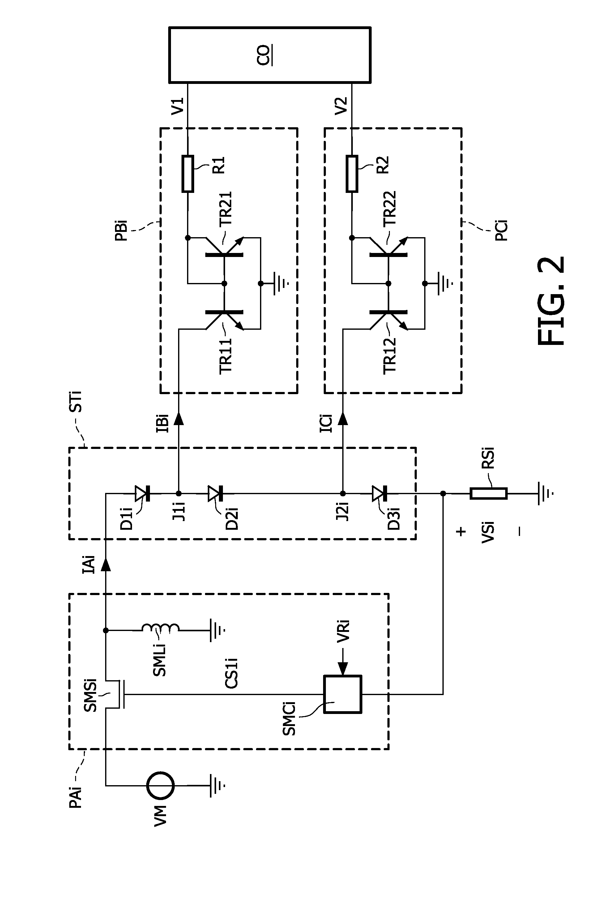
[0022]Three power supplies PAi, PBi, PCi are associated with each of the strings STi. The main power supply PAi ...


PUM


Abstract

The present invention relates to a driver for a string (STi) of series arranged light emitting diodes (D1i, D2i, D3i) of which at least two emit light having different spectra. The driver comprises a main power supply (PAi) which has outputs coupled across the string (STi) to supply a main current (IAi) to the string (STi). A secondary power supply (PBi) is coupled to at least one of junctions (J1i) between successive light emitting diodes (D1i, D2i) in the string (STi) to supply or withdraw a delta current (IBi) from the junction (J1i). The delta current (IBi) is at least a factor 5 smaller than the main current (IAi). A controller (CO) controls the secondary power supply (PBi) to generate the delta current (IBi) to obtain a desired spectral composition of the mixed light emitted by the string (STi).

Description

FIELD OF THE INVENTION[0001]The invention relates to a driver for a string of series arranged light emitting diodes, to a system of a driver and the string of light emitting diodes, to a backlight unit for illuminating a display panel, to a system comprising the backlight unit and the display panel, and to a display apparatus comprising the backlight unit and the display panel.BACKGROUND OF THE INVENTION[0002]WO 02 / 076150 A1 discloses an apparatus which controls multiple light sources of which the light is mixed to obtain light of a predetermined color light. A processor compares the amount of light detected of each of the light sources with a desired amount and controls drivers of the light sources such that the light sources produce the desired light level. The light sources are three strings of red, blue and green light emitting diodes (further also referred to as LED's), respectively. Each string of LED's is driven by a separate switched mode power supply (further also referred ...

Claims


Application Information

Patent Timeline
Patent Type & Authority Applications(United States)
IPC IPC(8): H05B37/02H05B44/00
CPCH05B33/0815H05B33/0857H05B33/083H05B45/48H05B45/20H05B45/3725
Inventor PEETERS, HENRICUS MARIEVAN WOUDENBERG, ROELBREMER, PETRUS JOHANNES
Owner SIGNIFY HLDG BV
Why Eureka
Try Eureka