Azimuthally sensitive resistivity logging tool

a resistivity logging and azimuthally sensitive technology, applied in the field of drilling, can solve the problems of inconvenient and time-consuming, inconvenient logging, and generally lack of ability to pinpoint the location of anomalies,

a resistivity logging and azimuthally sensitive technology, applied in the field of drilling, can solve the problems of inconvenient and time-consuming, inconvenient logging, and generally lack of ability to pinpoint the location of anomalies,

US20120212229A1Inactive Publication Date: 2012-08-23CHONGQING BROADCASTING GROUP

Image

  • Azimuthally sensitive resistivity logging tool
  • Azimuthally sensitive resistivity logging tool
  • Azimuthally sensitive resistivity logging tool

Examples


Embodiment Construction

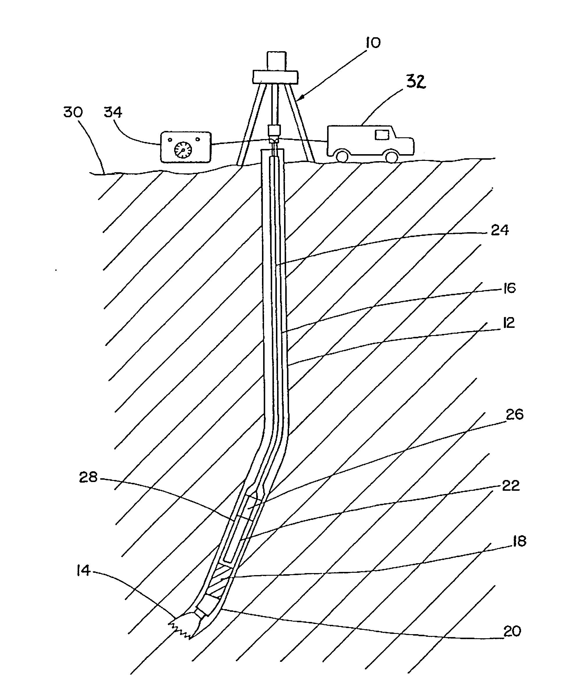
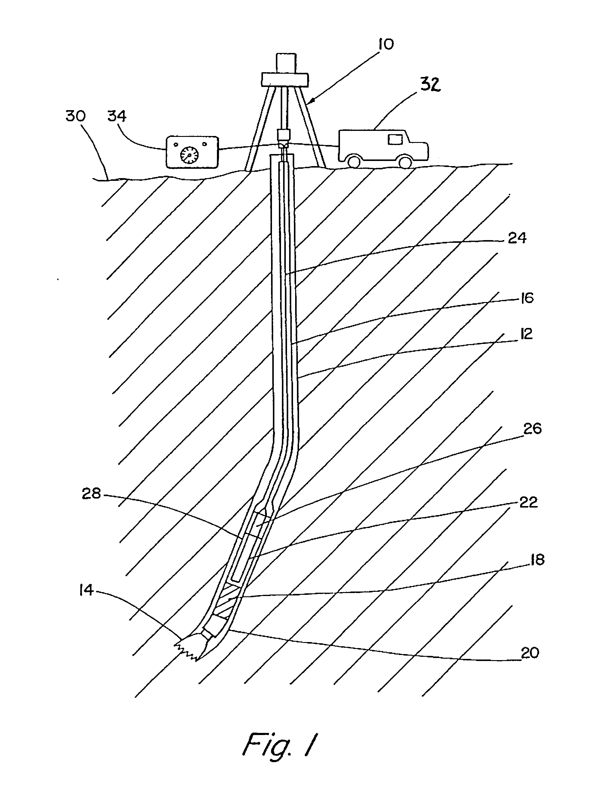
[0018]FIG. 1 illustrates how a drilling operation employs drilling rig 10 to cut a borehole 12 into the earth, penetrating the subsurface geological formation. Drillstring 16 passes through borehole 12 and is coupled between drilling rig 10 and a drill bit 14. Drillstring 16 includes drill bit 14, drill collars 28, and drill pipe.

[0019]The lowest part of drillstring 16 is made up of drill collars 28. Drill collars 28 are heavy walled pipe that provide weight on drill bit 14 and strength to resist buckling under their own weight. The drill pipe is thinner walled. The drill pipe is kept in tension (which may be effected by collars 28 placing weight on drill bit 14) to prevent buckling. Drill collars 28 may have radial projections (not shown) called stabilizers. Short drill collars, which may be adapted for specialized functions, are called “subs,” and references herein to drill collars are intended to include subs.

[0020]Drilling rig 10 turns drill bit 14, which cuts through the rock a...


PUM


Abstract

Various systems and methods for implementing an azimuthally sensitive resistivity logging tool are disclosed. One such method involves transmitting a primary magnetic field from one or more coils placed on a drill collar and receiving several electrical signals, where each of the electrical signals is received from a respective one of several sensors. The sensors are distributed around a circumference of a drill collar, and an axis of at least one of the sensors is perpendicular to an axis of the drill collar. Each of the electrical signals indicates a respective magnitude of a measurement of a reflected magnetic field, where the reflected magnetic field is reflected from an anomalous geological formation. The method calculates a vector measurement of the reflected magnetic field, based upon the electrical signals.

Description

CROSS-REFERENCE TO RELATED APPLICATIONS[0001]This application is a continuation of U.S. patent application Ser. No. 12 / 268,038, entitled “Azimuthally Sensitive Resistivity Logging Tool,” filed Nov. 10, 2008 and issued as U.S. Pat. No. 8,120,361, and naming Paul L. Sinclair and Joseph K. Clontz as the inventors. This application is assigned to CBG Corporation, the assignee of the present invention, and is hereby incorporated by reference in its entirety and for all purposes as if completely and fully set forth herein.FIELD OF THE INVENTION[0002]This invention relates to the field of logging while drilling, particularly as used in oil and gas development and exploration.DESCRIPTION OF THE RELATED ART[0003]Logging is a technique that is used to measure one or more characteristics, such as resistivity, of subsurface geologic formations. Such a measurement can be used, for example, to determine the type of subsurface formation surrounding a drill bit. Accordingly, logging provides useful...

Claims


Application Information

Patent Timeline
23 Aug 2012
Publication
US20120212229A1
IPC
G01V3/08
CPC
G01V3/28
Inventors
SINCLAIR, PAUL L.; CLONTZ, JOSEPH K.