Overvoltage protection element

a protection element and overvoltage technology, applied in overvoltage protection resistors, spark gap details, relays, etc., can solve the problems of varistor electrical disconnection, solder connection melting, solder connection continuously loaded with shear stress, etc., and achieve the effect of increasing volum

Inactive Publication Date: 2012-09-13
PHOENIX CONTACT GMBH & CO KG
View PDF35 Cites 18 Cited by
  • Summary
  • Abstract
  • Description
  • Claims
  • Application Information

AI Technical Summary

Benefits of technology

[0036]Generally, the thermally expandable material is made such that the volume increase is irreversible. But, a suitable choice of the propellant and carrier material can also result in that the carrier material, upon cooling, being transferred back into its initial state so that the volume increase of the material can be made reversible.

Problems solved by technology

Unacceptable heating of the varistor here also leads to heating of the solder site so that the slide is pulled out of the connection site between the first connection element and the terminal lug as a result of the force of a spring acting on it; this leads to electrical disconnection of the varistor.
If unacceptable heating of the varistor occurs, this leads to melting of the solder connection.
But, the problem is that the solder connection is continuously loaded with a shear stress in the normal state of the overvoltage protection element as a result of the spring force of the spring element or the isolating tongue which has been deflected out of its rest position.

Method used


Image

  • Overvoltage protection element
  • Overvoltage protection element
  • Overvoltage protection element

Examples


Embodiment Construction

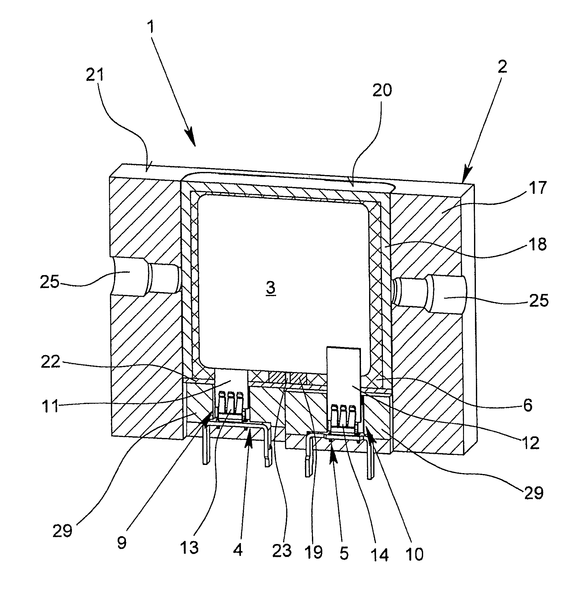
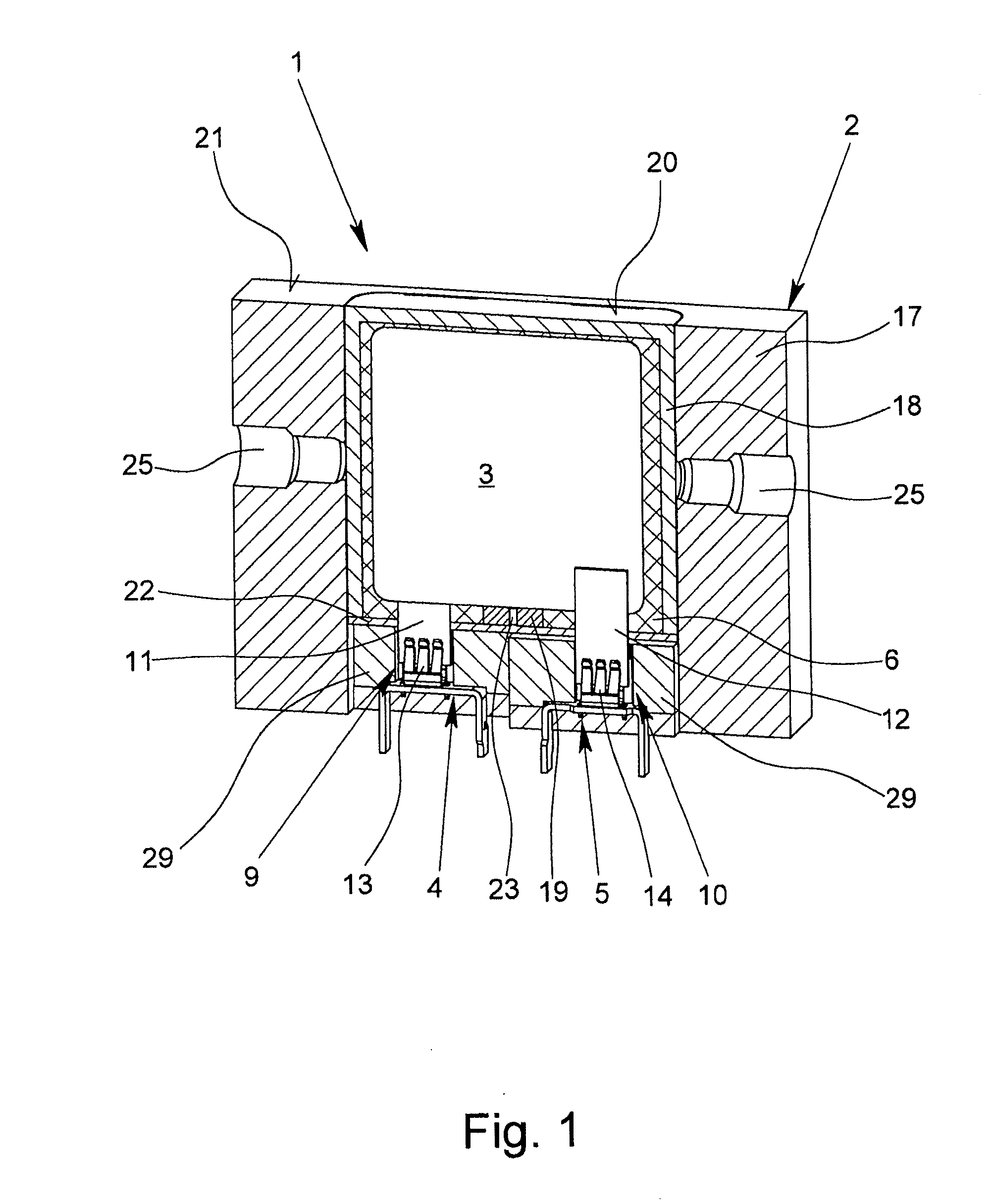
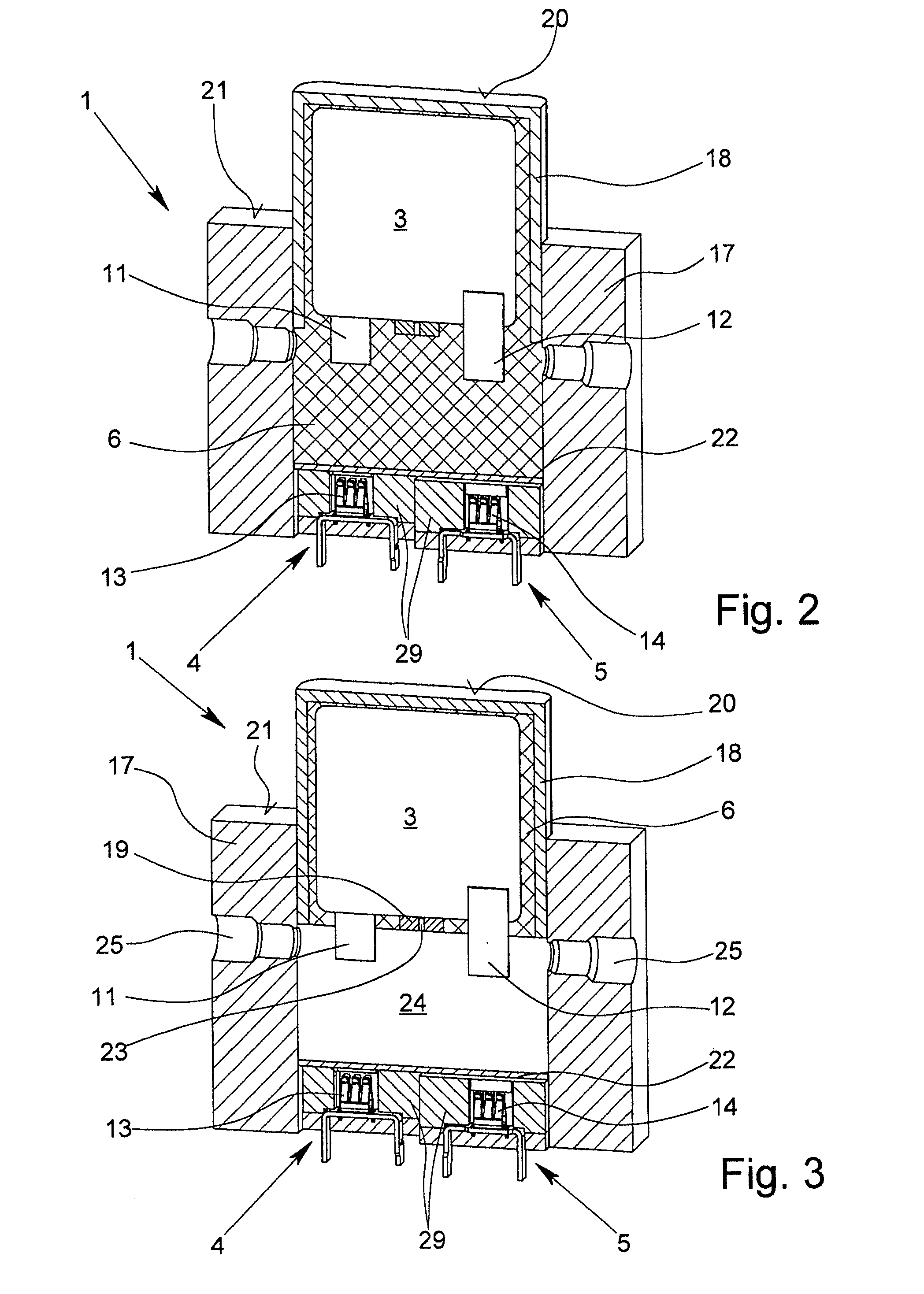
[0051]The figures show an overvoltage protection element 1 with a housing 2, and an overvoltage limiting component located in the housing 2. In the exemplary embodiment according to FIGS. 1 to 3, the overvoltage limiting component is a varistor 3, while the overvoltage protection elements 1 according to FIGS. 4 to 12 use a gas-filled surge arrester 3′.

[0052]The overvoltage protection element 1 according to FIGS. 1 to 3 can be made as a protective plug having two connection elements 4, 5 which can be inserted into corresponding receptacles of the lower part of a device (not shown). The connection elements 4, 5 are each connected to a pole of the varistor 3 in the normal state of the overvoltage protection element 1 so that the varistor 3 can be connected via the two connection elements 4, 5 to the current path or signal path which is to be protected.

[0053]As is apparent from FIGS. 1, 4 and 7, in the normal state of the overvoltage protection element 1, a thermally expandable material...


PUM


Abstract

An overvoltage protection element with a housing, an overvoltage-limiting component arranged in the housing, and with two connection elements for electrically connecting the overvoltage protection element to the current or signal path to be protected, wherein, normally, the connection elements are each in electrically conductive contact with a pole of the overvoltage-limiting component. Reliable and effective electrical connection in the normal state and reliable isolation of a defective overvoltage-limiting component are ensured by the fact that a thermally expandable material is arranged within the housing in a way that, in the event of thermal overloading of the overvoltage-limiting component, the position of the overvoltage-limiting component is changed by expansion of the thermally expandable material relative to the position of the connection elements in a way that causes at least one pole of the overvoltage-limiting component to be out of electrically conductive contact with the corresponding connection element.

Description

BACKGROUND OF THE INVENTION[0001]1. Field of the Invention[0002]The invention relates to an overvoltage protection element with a housing, with at least one overvoltage limiting component which is located in the housing, especially a varistor or a gas filled surge arrester, and with at least two connection elements for electrical connection of the overvoltage protection element to the current path or signal path which is to be protected, in the normal state of the overvoltage protection element the connection elements each being in electrically conductive contact with one pole of the overvoltage limiting component at a time.[0003]2. Description of Related Art[0004]German Patent Application DE 42 41 311 A1 discloses an overvoltage protection element which has a thermal disconnector for monitoring of the state of a varistor. In this overvoltage protection element, the first connection element is connected via a flexible conductor to a rigid isolating element whose end facing away from...

Claims


Application Information

Patent Timeline
Patent Type & Authority Applications(United States)
IPC IPC(8): H01H71/14
CPCH01C7/12H01H37/46H01H37/74H01H2037/769H01H1/20H01C7/126H01H37/767H01T1/14H01H37/04H01H37/36
Inventor DEPPING, CHRISTIANDURTH, RAINERFINIS, GERNOTMEYER, THOMASCHRIST, ANDREAS
Owner PHOENIX CONTACT GMBH & CO KG
Why Eureka
Try Eureka