Anvil Roll System and Method

a technology of anvil roll and rotary cutting, which is applied in the field of rotary cutting equipment, can solve the problems of undesirable deflection of anvil roll, wear of outer surface of anvil roll, and difficulty in controlling the rotation of anvil roll

Inactive Publication Date: 2012-09-20
THE PROCTER & GAMBLE COMPANY
View PDF5 Cites 42 Cited by
  • Summary
  • Abstract
  • Description
  • Claims
  • Application Information

AI Technical Summary

Problems solved by technology

As the cutting member on the die roll cuts the material, an outer surface of the anvil roll may wear owing to the pressure applied by the cutting member to the outer surface of the anvil roll.
Additionally, as the die roll engages the anvil roll, undesirable deflection in the anvil roll may occur.
As the size of the anvil roll increases, difficulties in controlling the rotation of the anvil roll may result.
For instance, as the mass of the anvil roll increases, it is typically more difficult to start, stop, or otherwise control the rotation of the anvil roll.
Anvil rolls having a larger diameter

Method used


Image

  • Anvil Roll System and Method
  • Anvil Roll System and Method
  • Anvil Roll System and Method

Examples


Embodiment Construction

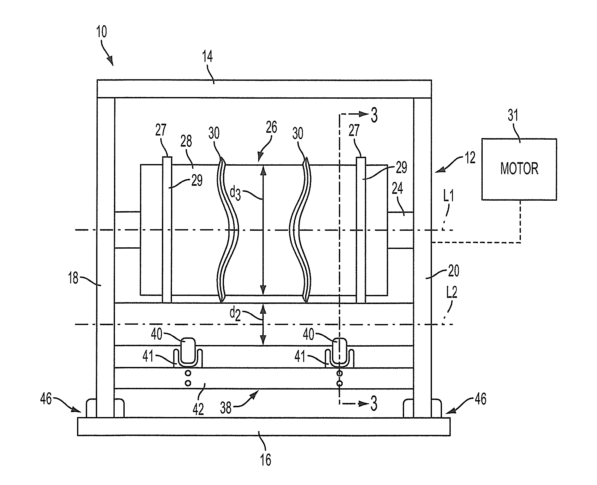
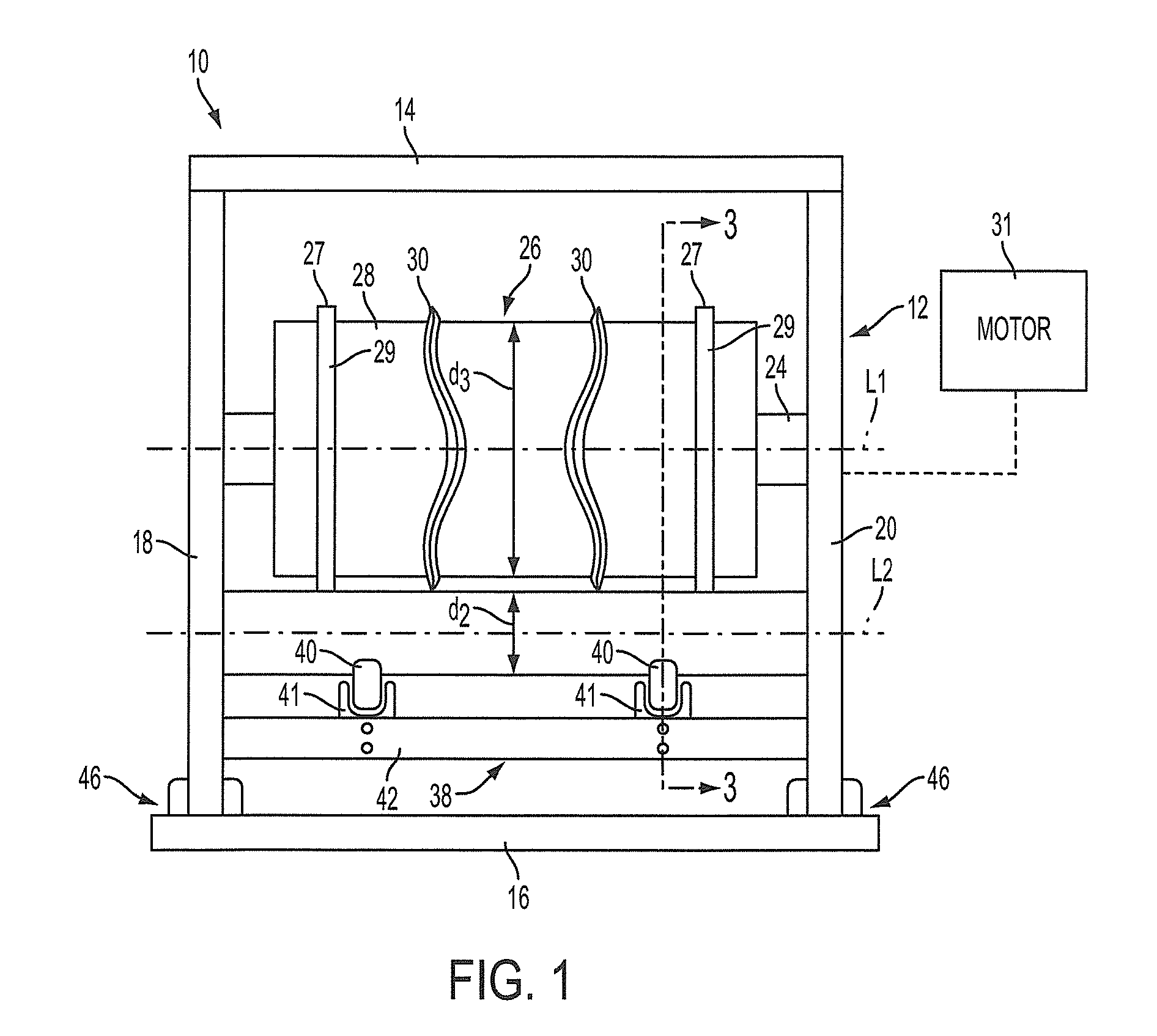
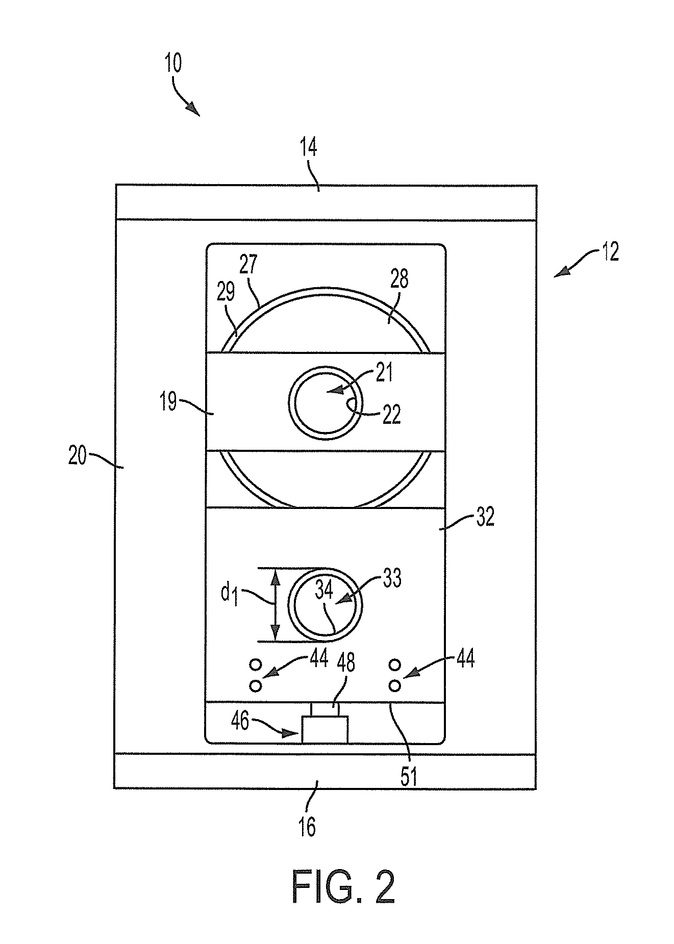
[0016]Various non-limiting embodiments of the present disclosure will now be described to provide an overall understanding of the principles of the structure, function, manufacture, and use of the apparatuses and methods disclosed herein. One or more examples of these non-limiting embodiments are illustrated in the accompanying drawings. Those of ordinary skill in the art will understand that the apparatuses and methods specifically described herein and illustrated in the accompanying drawings are non-limiting example embodiments and that the scope of the various non-limiting embodiments of the present disclosure are defined solely by the claims. The features illustrated or described in connection with one non-limiting embodiment may be combined with the features of other non-limiting embodiments. Such modifications and variations are intended to be included within the scope of the present disclosure.

[0017]The present disclosure provides rotary cutting apparatuses and methods utiliz...


PUM

PropertyMeasurementUnit
Diameteraaaaaaaaaa
Lengthaaaaaaaaaa
Speedaaaaaaaaaa

Abstract

A rotary cutting apparatus comprising a frame and a die roll defining a first longitudinal axis and comprising a cutting member. The die roll is rotatably connected with the frame and configured to rotate about the first longitudinal axis. The rotary cutting apparatus further comprises a bearer ring connected with the die roll and an anvil roll defining a second longitudinal axis and comprising an outer radial surface. The anvil roll is rotatably connected with the frame and is configured to rotate about the second longitudinal axis. The bearer ring of the die roll is in contact with the outer radial surface. The anvil roll may be supported by at least one cam follower. The anvil roll may be axially removable from the frame via lateral translation along the second longitudinal axis.

Description

FIELD OF THE INVENTION[0001]The present disclosure relates generally to rotary cutting apparatuses and, more particularly, relates to methods and apparatuses using anvil roll having a relatively small diameter and being laterally removable from a frame to allow online replacement.BACKGROUND OF THE INVENTION[0002]Rotary cutting apparatuses can comprise a frame, a die roll rotatably mounted to the frame, and an anvil roll rotatably mounted to the frame. The die roll can comprise at least one cutting member for cutting and creasing material against an anvil roll when the material is passed between the die roll and the anvil roll. As the cutting member on the die roll cuts the material, an outer surface of the anvil roll may wear owing to the pressure applied by the cutting member to the outer surface of the anvil roll. Eventually, the anvil roll may need to be replaced after a sufficient amount of the outer surface of the anvil roll has been worn away. Additionally, as the die roll eng...

Claims


Application Information

Patent Timeline
IPC IPC(8): B26D1/22B26D3/08
CPCB26D7/204B26D7/265B26D1/405B26D1/285B26D1/40B26F1/384Y10T83/0605Y10T83/4838
Inventor KANDEMIR, MUJDAT
Owner THE PROCTER & GAMBLE COMPANY
Why Eureka
Try Eureka