Autonomous Sump Pump System

automatic technology, applied in the direction of positive displacement liquid engines, instruments, machines/engines, etc., can solve the problems of current sump pump systems not providing for the operation of a sump pump system, and the sump pump system cannot remove water from a sump well

Inactive Publication Date: 2012-10-04
IRWIN IV DAVID LEONARD +2
View PDF4 Cites 14 Cited by
  • Summary
  • Abstract
  • Description
  • Claims
  • Application Information

AI Technical Summary

Problems solved by technology

When the commercial power utility line fails to deliver electrical power to the building, a sump pump system cannot remove water from a sump well until electrical power is restored.
Current sump pump systems do not provide for a sump pump system operation during extended power outages.

Method used


Image

  • Autonomous Sump Pump System
  • Autonomous Sump Pump System
  • Autonomous Sump Pump System

Examples


Embodiment Construction

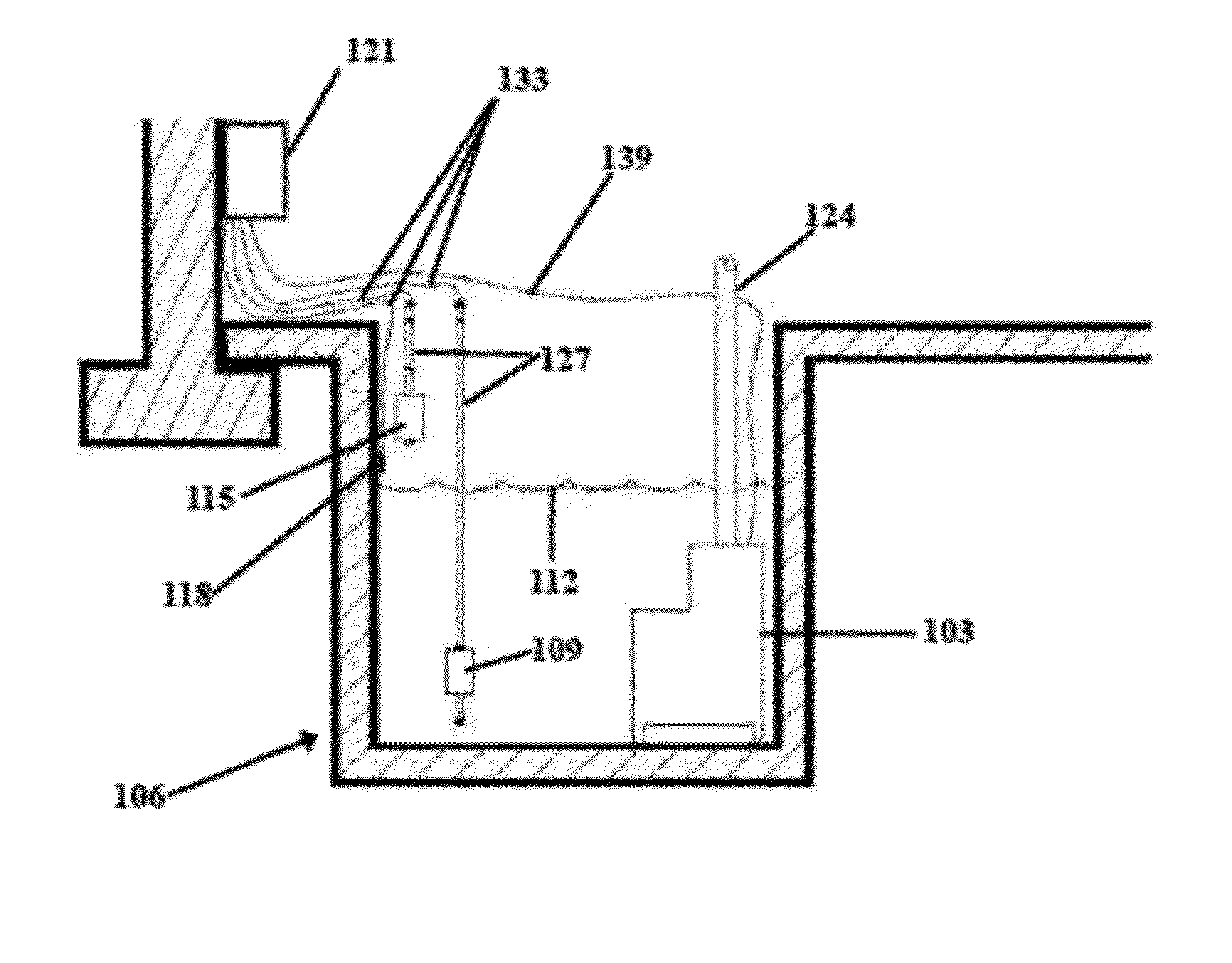
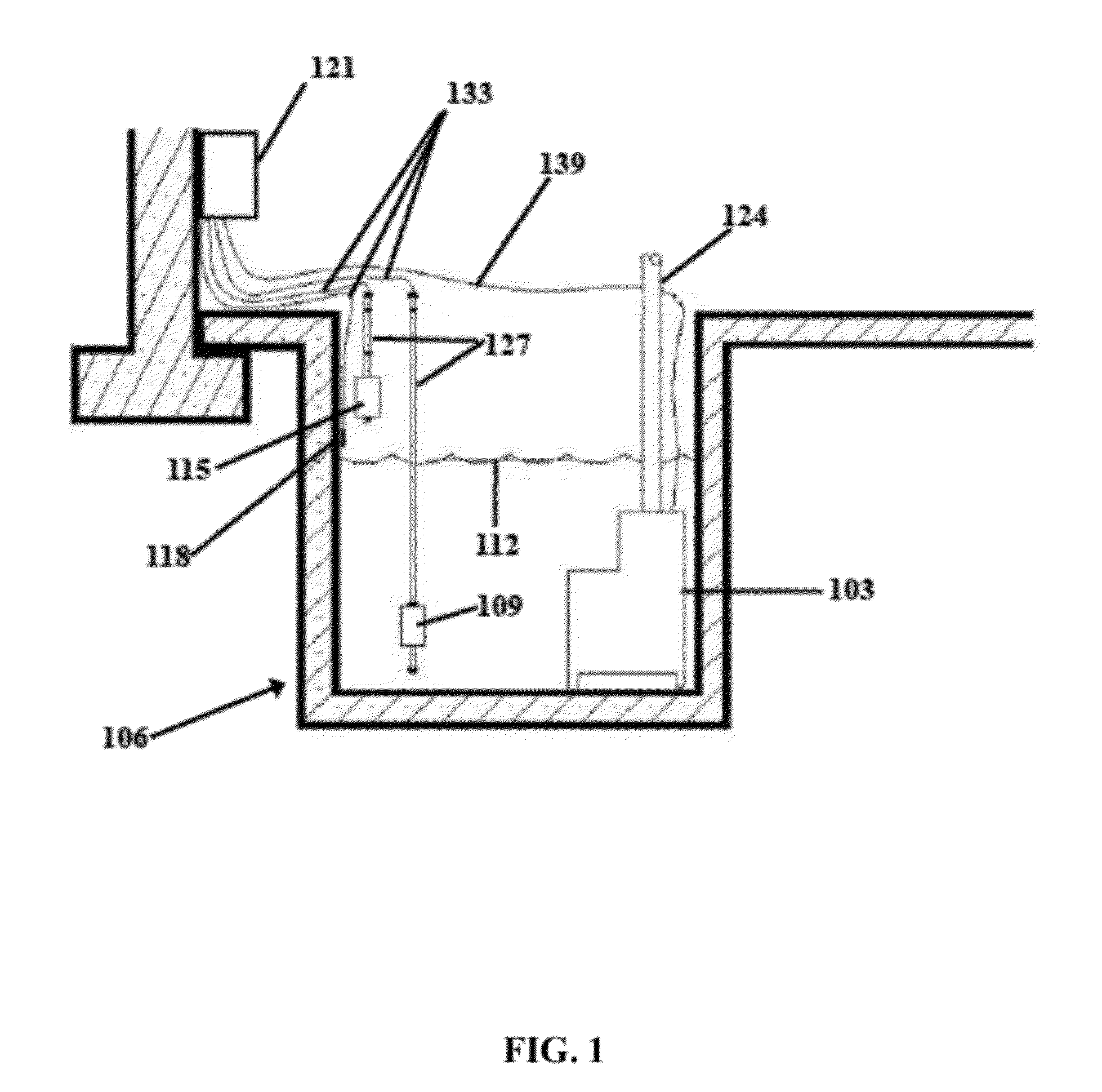
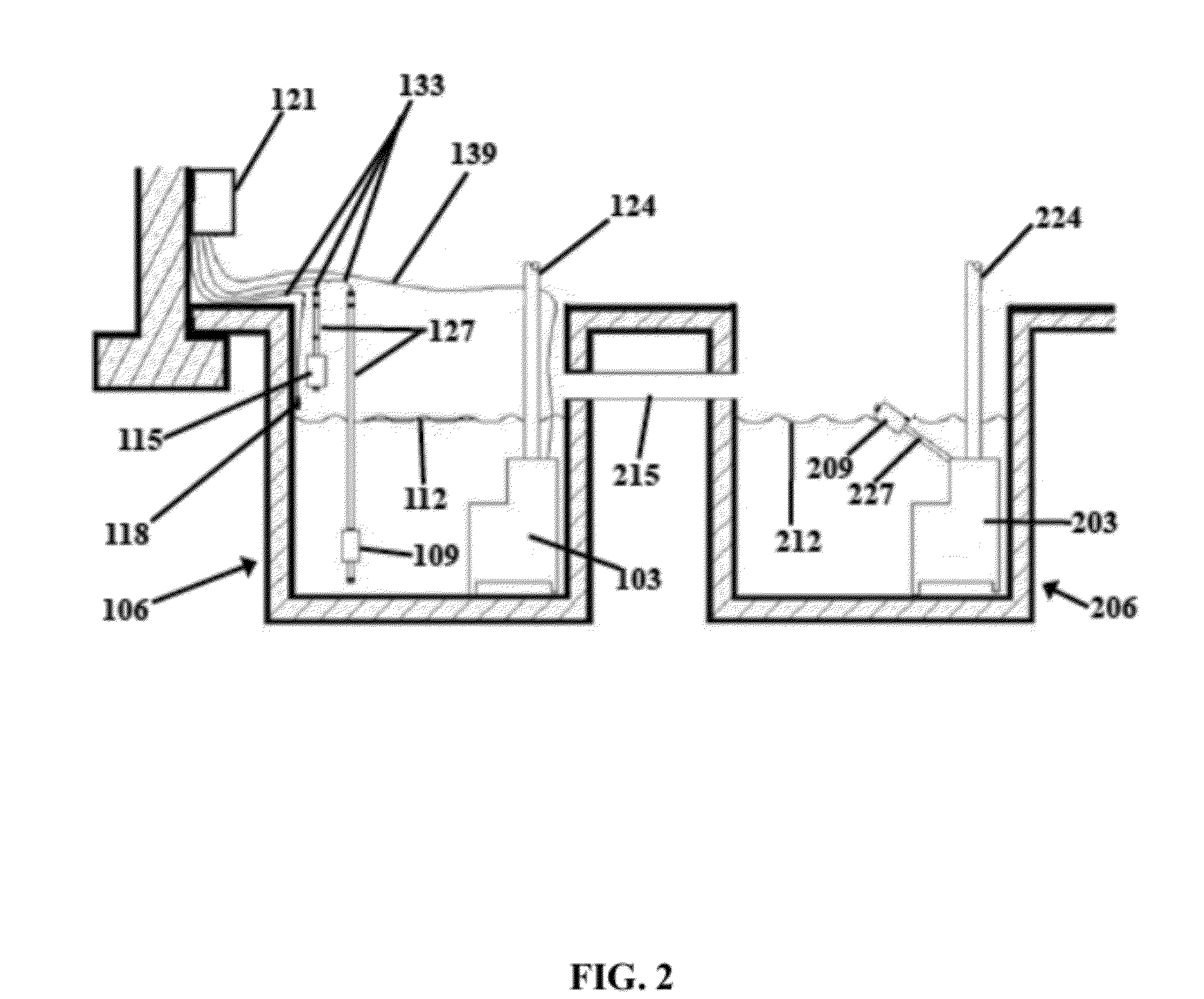
[0018]Reference is now made in detail to the description of the embodiments as illustrated in the drawings. While several embodiments are described in connection with these drawings, there is no intent to limit the disclosure to the embodiment or embodiments disclosed herein. On the contrary, the intent is to cover all alternatives, modifications, and equivalents.

[0019]Traditional sump pump systems are designed to rely solely on commercial electric power or a whole building generator, which supplies power to an entire building. Thus, traditional sump pump systems cannot remove water from a sump well during a power outage. To solve the problem of traditional sump pump system failure during a power outage, some sump pump systems are designed to have a secondary power source. Typically, the secondary power source is a battery, which suffers from a limited battery life, providing only a few hours of power to the sump pump system. Thus, the use of a battery as a second power source does ...


PUM


Abstract

An autonomous sump (ASP) system is designed to remove water from a sump using a source of power other than commercial electrical power or battery power. The ASP system can be a stand-alone unit or, alternatively, can be used along with a preexisting sump pump system. In some embodiments, the ASP system can provide an alert to a building owner of the ASP system failure.

Description

CROSS-REFERENCE TO RELATED APPLICATIONS[0001]This application claims the benefit of U.S. provisional patent application Ser. No. 61 / 471,145, filed 2011 Apr. 2, having the title Automatic Sump Pump System, which is incorporated herein by reference in its entirety.STATEMENT REGARDING FEDERALLY SPONSORED RESEARCH OR DEVELOPMENT[0002]Not ApplicableTHE NAMES OF PARTIES TO A JOINT RESEARCH AGREEMENT[0003]Not ApplicableINCORPORATION BY REFERENCE OF MATERIAL SUBMITTED ON A COMPACT DISC[0004]Not ApplicableBACKGROUND[0005]1. Technical Field[0006]The present disclosure relates generally to sump pump systems and, more particularly, to autonomous notification and removal of water from a sump well.[0007]2. Description of the Related Art[0008]Traditional sump pump systems are powered off a building's power supply, which is typically connected to a commercial power utility line provided by a commercial electric provider. When the commercial power utility line fails to deliver electrical power to th...

Claims


Application Information

Patent Timeline
Patent Type & Authority Applications(United States)
IPC IPC(8): F04B49/04F04B17/03
CPCE03F5/22F04B17/03F04D13/068F04D15/0218F04B49/025G01F23/261G01F23/265G01F23/266
Inventor IRWIN, DAVID LEONARDTAYLOR, III, FITZ-WILLIAM BYRDIRWIN, WILLIAM SPENCER
Owner IRWIN IV DAVID LEONARD
Why Eureka
Try Eureka