Cooling system for a photocosmetic device

a photocosmetic device and cooling system technology, applied in the field of photocosmetic devices, can solve the problems of significant pain and/or infection risk, destructive heating of target structures located in the epidermis/dermis of a patient's skin, and the limitations of the current available photocosmetic devices

Inactive Publication Date: 2006-07-06
PALOMAR MEDICAL TECH
View PDF99 Cites 161 Cited by
  • Summary
  • Abstract
  • Description
  • Claims
  • Application Information

AI Technical Summary

Problems solved by technology

Currently, photocosmetic procedures are performed using professional-grade devices that cause destructive heating of target structures located in the epidermis / dermis of a patient's skin.
To date, photocosmetic procedures have been performed in a dermatologist's office, partially because of the expense of the devices used to perform the procedures, partially because of safety concerns related to the devices, and partially because of the need to care for optically induced wounds on the patient's skin.
Such wounds may arise from damage to a patient's epidermis caused by the high-power radiation and may result in significant pain and / or risk of infection.
Currently available photocosmetic devices have limitations related to one or more of the above challenges.

Method used


Image

  • Cooling system for a photocosmetic device
  • Cooling system for a photocosmetic device
  • Cooling system for a photocosmetic device

Examples


Embodiment Construction

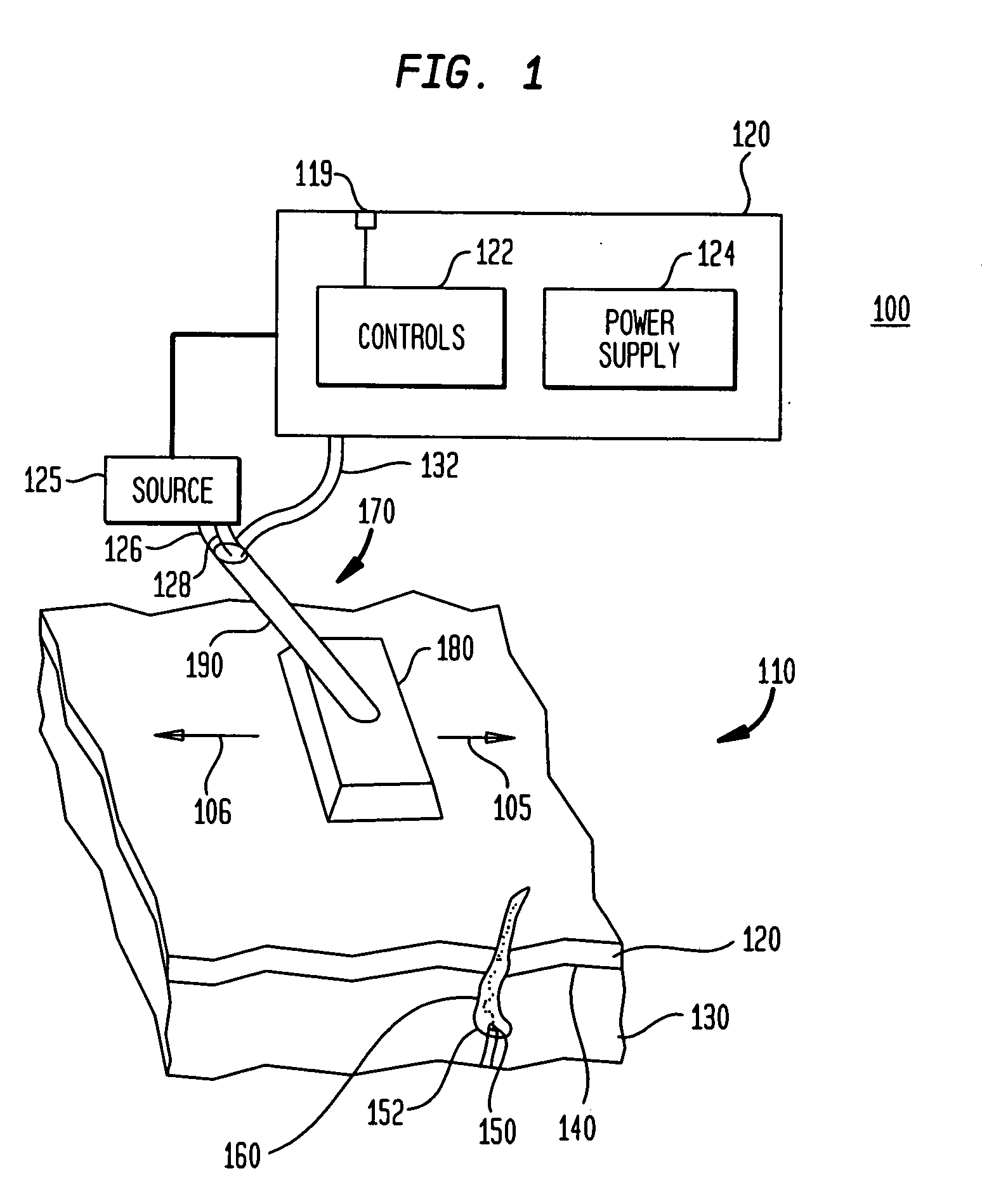
[0065]FIG. 1 is a schematic illustration of some basic elements of a photocosmetic device 100 according to some aspects of the present invention. Area 110 is an area of a patient's skin on which a selected photocosmetic treatment is to be performed. Area of skin 110 has a basal layer 140 in between an epidermal layer 120 and a dermal layer 130. Typically, photocosmetic treatments involve treating a target area located within epidermal layer 120 or dermal layer 130. For example, in the case of hair removal, it may be desirable to heat a bulb 150 of a hair follicle 160. Alternatively, only a portion of bulb 150 may be heated, for example, the basement membrane 152 between the papilla and the follicle.

[0066] In some embodiments of the present invention, the major sub-systems of device 100 include a handpiece 170, a base unit 120 and cord 126 to couple handpiece 170 to base unit 120. Base unit 120 may include a power supply 124 to power control electronics 122 and electromagnetic radia...


PUM


Abstract

Photocosmetic device for use in medical or non-medical environments (e.g., a home, barbershop, or spa), which can be used for a variety of tissue treatments. Radiation is delivered to the tissue via optical systems designed to pattern the radiation and project the radiation to a particular depth. The device has a variety of cooling systems including phase change cooling solids and liquids to cool treated skin and the radiation sources. Contact sensors and motion sensor may be used to enhance treatment. The device may be modular to facilitate manufacture and replacement of parts.

Description

RELATED APPLICATIONS [0001] This application claims priority to provisional application Ser. No. 60 / 363,798, filed Mar. 12, 2002. This application is also a continuation-in-part of application Ser. No. 10 / 052,474, filed Jan. 18, 2002, which application is a continuation of application Ser. No. 09 / 473,910, filed Dec. 28, 1999, which application claims priority to provisional application Ser. No. 60 / 115,447, filed Jan. 8, 1999, claims priority from provisional application Ser. No. 60 / 164,492, filed Nov. 9, 1999, and is a continuation-in-part of application Ser. No. 09 / 078,055, filed May 13, 1998, now U.S. Pat. No. 6,273,884, which application claims priority to provisional application Ser. No. 60 / 046,542, filed May 15, 1997 and provisional application Ser. No. 60 / 077,726, filed Mar. 12, 1998. This application is also a continuation-in-part of application Ser. No. 09 / 268,433, filed Mar. 12, 1999, which application claims priority to provisional application Ser. No. 60 / 115,447, filed Ja...

Claims


Application Information

Patent Timeline
Patent Type & Authority Applications(United States)
IPC IPC(8): A61N5/06A61B18/00A61B17/00A61B18/20A61F7/00A61N5/00
CPCA45D26/0061A45D44/005A61B18/203A61B2017/00026A61B2017/00747A61B2017/00765A61B2017/00769A61B2018/00011A61B2018/00029A61B2018/00452A61B2018/00476A61B2018/00904A61B2019/465A61N1/328A61B2090/065
Inventor ALTSHULER, GREGORY B.CARUSO, JOSEPH P.ZENZIE, HENRY H.BURKE, JAMES G. IIIEFROFEEV, ANDREI V.
Owner PALOMAR MEDICAL TECH
Why Eureka
Try Eureka