
Airborne GPS guidance system for defeating multiple jammers

a gps guidance and multiple jammer technology, applied in direction controllers, instruments, using reradiation, etc., can solve the problems of low power jammer, low cost jammer scattered around target area, and inability to achieve low-power jammer,

Inactive Publication Date: 2001-10-09
SCHNEIDER ARTHUR J +1
View PDF9 Cites 173 Cited by
  • Summary
  • Abstract
  • Description
  • Claims
  • Application Information

AI Technical Summary

Benefits of technology

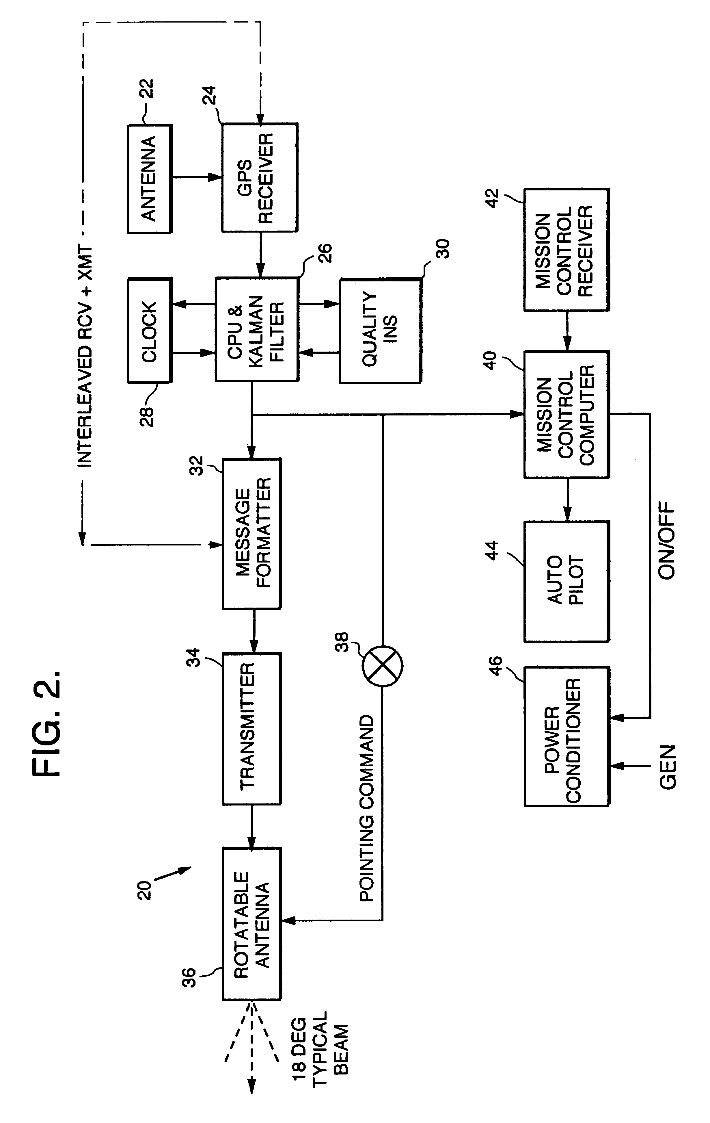
In a particular implementation, the position of each pseudolite is predicted and transmitted to the missile to remove the effect of transmission delay. The use of three pseudolites allows for the calculation of x, y position and time (t). A fourth pseudolite could be used to provide for x, y, z, and t determination onboard the missile. However, in the preferred embodiment, the missile is equipped with an altimeter for the purpose of ascertaining the elevation of the missile.

Problems solved by technology

Unfortunately, GPS guidance, which uses 10 watt signals from satellites in an 11,000 nautical mile orbit, is notoriously easy to jam with low power, low cost jammers scattered around a target area.
Though somewhat effective, this approach can be expensive as the number of jammers that can be nullified is one less than the number of antenna elements.
Hence, the effectiveness of this limited approach is questionable if a large number of inexpensive jammers are used.
To succeed as a jammer, a 1 watt jammer, successful against GPS satellites, would need 100,000 watts or 1 megawatt of power to succeed against aircraft carried pseudolites, which would not be feasible economically at the time of filing of the present application.

Method used


Image

  • Airborne GPS guidance system for defeating multiple jammers
  • Airborne GPS guidance system for defeating multiple jammers
  • Airborne GPS guidance system for defeating multiple jammers

Examples


Embodiment Construction

Illustrative embodiments and exemplary applications will now be described with reference to the accompanying drawings to disclose the advantageous teachings of the present invention.

While the present invention is described herein with reference to illustrative embodiments for particular applications, it should be understood that the invention is not limited thereto. Those having ordinary skill in the art and access to the teachings provided herein will recognize additional modifications, applications, and embodiments within the scope thereof and additional fields in which the present invention would be of significant utility.

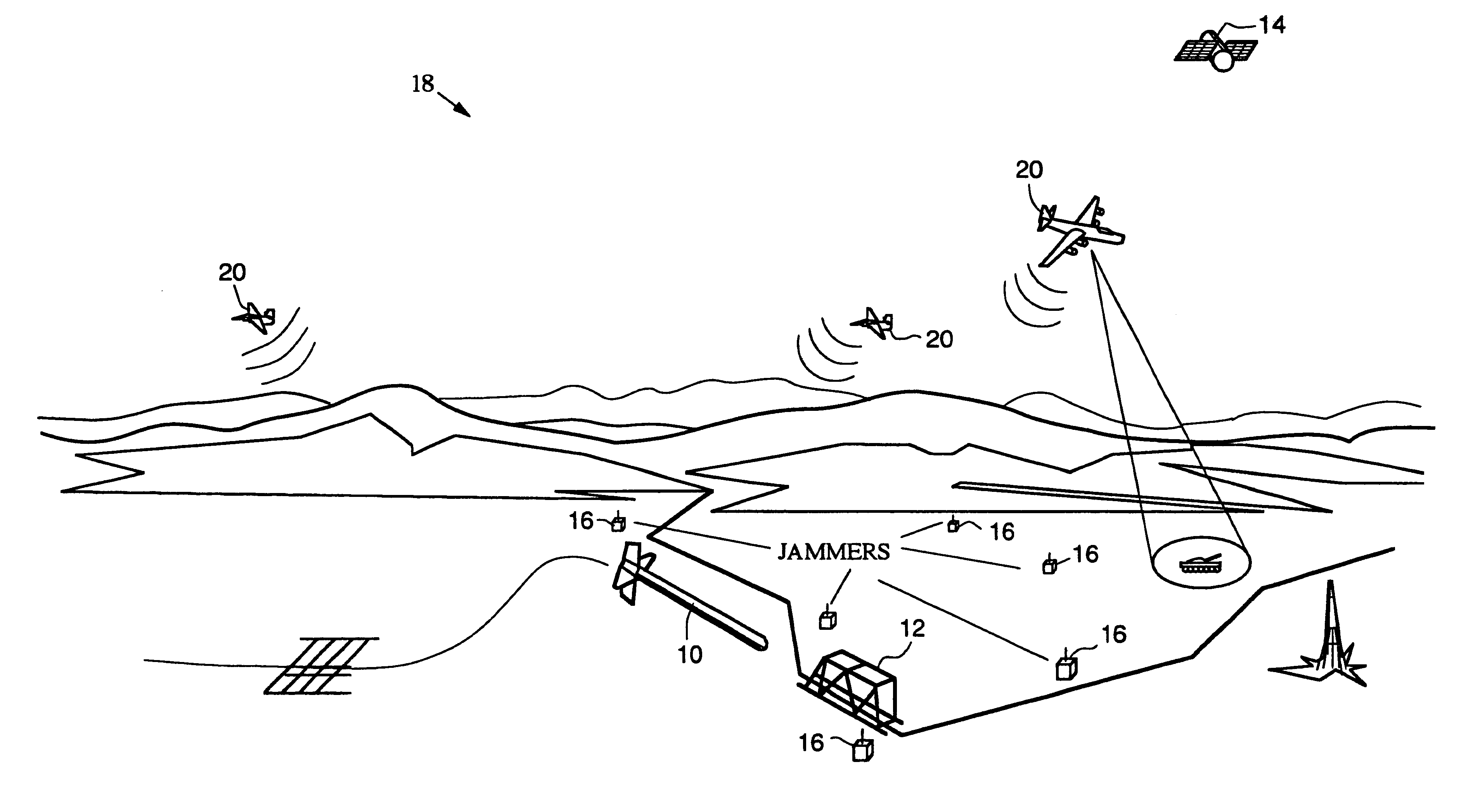
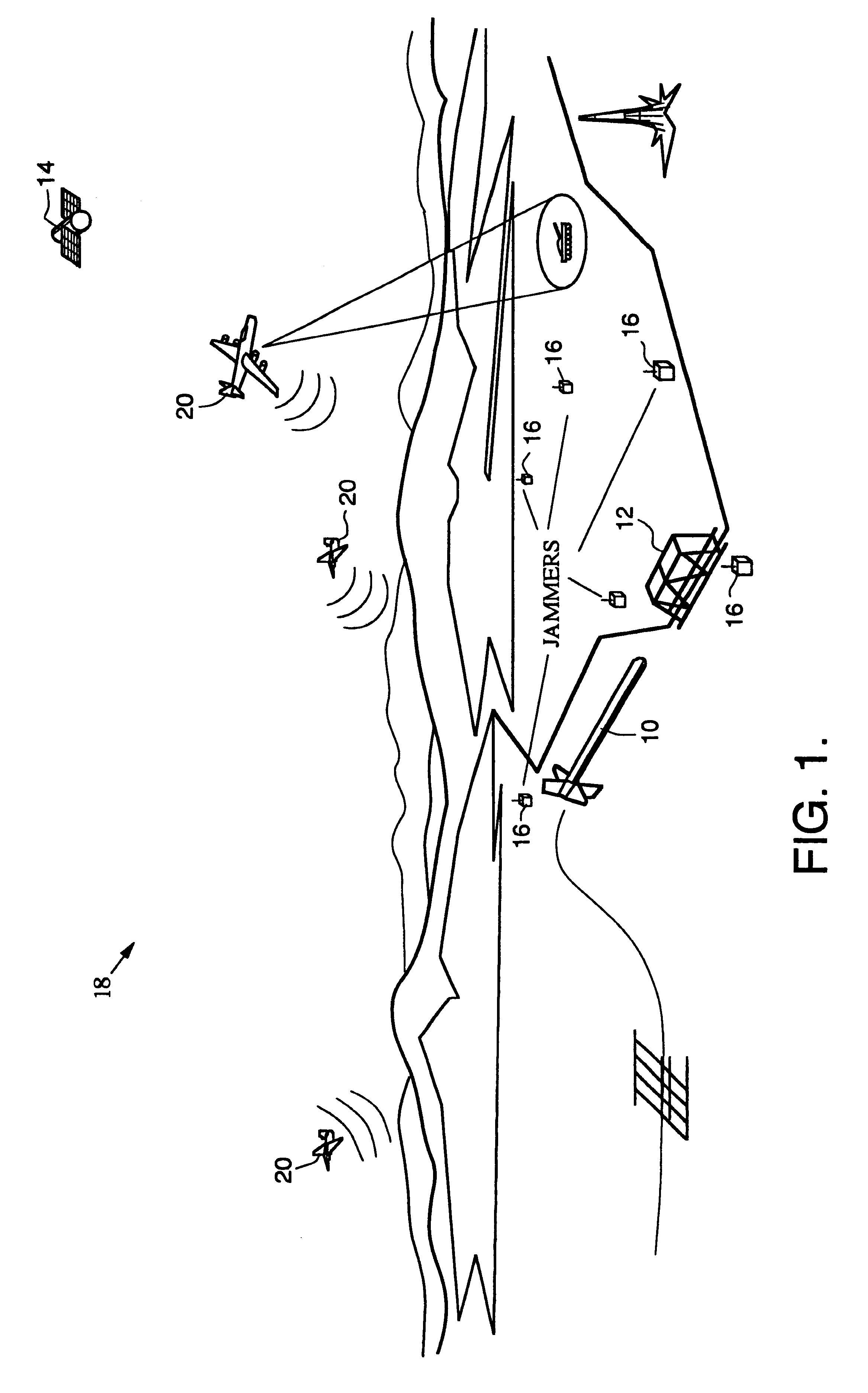
FIG. 1 is a diagram depicting the airborne GPS guidance system of the present invention in an operational environment. Conventionally, a missile 10 is guided to a target 12 using GPS signals from a satellite 14. Unfortunately, as mentioned above, a small number of low power (e.g. 1 watt), low cost jammers 16 may effectively defeat the system. When the GPS link i...


PUM


Abstract

A missile guidance system designed to operate on GPS signals in an anti-jamming environment. The inventive system includes first, second and third airborne vehicles (20). A GPS receiver (24) is mounted on each of the three vehicles (20) to receive signals transmitted from spaceborne satellites (14). Each vehicle (20) acts as a pseudo-satellite or "pseudolite'. The received GPS signals are processed by a processor (26) to provide a first intermediate signal indicating the position of the vehicle (20). This signal is retransmitted from each vehicle and received by a GPS receiver mounted on a missile. The received intermediate signal is processed on the missile to provide an output signal indicating the position thereof. The pseudolites would be airborne in the vicinity of a target area. Because the pseudolites are relatively close to the targets compared to a satellite in high altitude orbit and because the pseudolites would be able to transmit a kilowatt or more power, the signal strength may be improved significantly. To succeed as a jammer, a jammer, successful against GPS satellites, would need considerably more power to succeed against aircraft carried pseudolites. The pseudolite system delivers GPS signals into the target area 40-70 dB stronger than signals coming directly from GPS satellites. By timing the signals for 100% time coverage, enemy C / A code receivers will be jammed because they are limited to a J / S capability of 30 dB.

Description

1. Field of the InventionThe present invention relates to guidance systems. More specifically, the present invention relates to guidance for weapons systems using the Global Positioning System (GPS).2. Description of the Related ArtThe utility of the Global Positioning System for guidance applications is well recognized. The Global Positioning System is a network of satellites that transmits information in signals, which when received and decoded, allow a receiver to accurately fix its position within a coverage area. For military applications, GPS allows self-guided weapons to find targets with heretofore unknown degrees of accuracy.Unfortunately, GPS guidance, which uses 10 watt signals from satellites in an 11,000 nautical mile orbit, is notoriously easy to jam with low power, low cost jammers scattered around a target area. As a large number of units would be used to defend high value targets, one by one destruction of the jammers would have a low payoff. If only a few remain op...

Claims


Application Information

Patent Timeline
IPC IPC(8): G01S1/00G01S19/22
CPCG01S19/09G01S19/11G01S19/18G01S19/21H04K3/20H04K3/90H04K3/92H04K2203/22H04K2203/24F41G7/34G01S19/015G01S19/115H04K3/255H04K3/28
Inventor SCHNEIDER, ARTHUR J.SMALL, JAMES G.
Owner SCHNEIDER ARTHUR J
Learn More