
Quick change vise jaw system

a vise jaw and quick change technology, applied in the field of engineers' supervision, can solve the problems of deformation and error of finished workpieces, prone to rapid changeover, and the approach of fastening the detachable jaw to the locking jaw

Active Publication Date: 2012-10-11
BELLATEX INDS
View PDF17 Cites 3 Cited by
  • Summary
  • Abstract
  • Description
  • Claims
  • Application Information

AI Technical Summary

Benefits of technology

[0015]In accordance with the present invention, the fastening device includes a plurality of bores cut into the base of the locking jaw, a plurality of nut holes cut into a top surface and intersecting the first edge of the locking jaw. A plurality of studs is provided with a right-hand threaded segment, a left-hand threaded segment and an unthreaded segment separating the threaded segments. The right-hand threads are screwed into the bores in the base and a nut operatively engages the left-hand

Problems solved by technology

Hard jaws can lead to deformation and error of the finished work piece if the vise is over-tightened, or if the operator is unskilled or negligent in his handling of the work piece around hard jaws.
Because soft jaws are consumable items, it is desirable that they be susceptible to rapid changeover.
The approach of fastening the detachable jaw to the locking jaw after attachment in the '066 patent has manifest problems.
First, the assembly of the '066 patent is incapable of front loading the detachable jaw and requires that the detachable jaw be inserted from the side.
Second, it weakens the structural integrity of the locking jaw.
Third, because the locking jaw is made of a metal of greater strength than a soft detachable jaw, a great deal of force is required to pull the tapers toward each other to securely capture the dovetail of the detachable jaw.
This will strain the operator and add to the time necessary to change out the detachable jaw.
Fourth, the fastening approach of the '066 patent will still allow the detachable jaw to slip inside the dovetail groove if the pins do not adequately tighten the locking jaw to pull the tapers toward one another.

Method used


Image

  • Quick change vise jaw system
  • Quick change vise jaw system
  • Quick change vise jaw system

Examples


Embodiment Construction

[0023]The following discussion is presented to enable a person skilled in the art to make and use the present teachings. Various modifications to the illustrated embodiments will be readily apparent to those skilled in the art, and the generic principles herein may be applied to other embodiments and applications without departing from the present teachings. Thus, the present teachings are not intended to be limited to the embodiments shown, but are to be accorded the widest scope consistent with the principals and features disclosed herein.

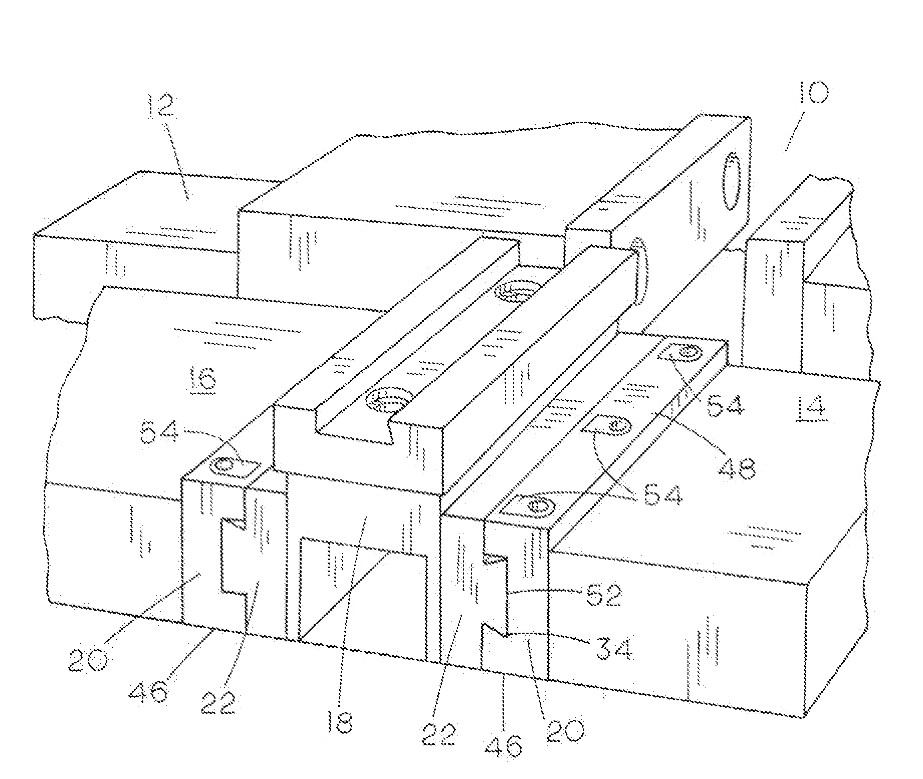
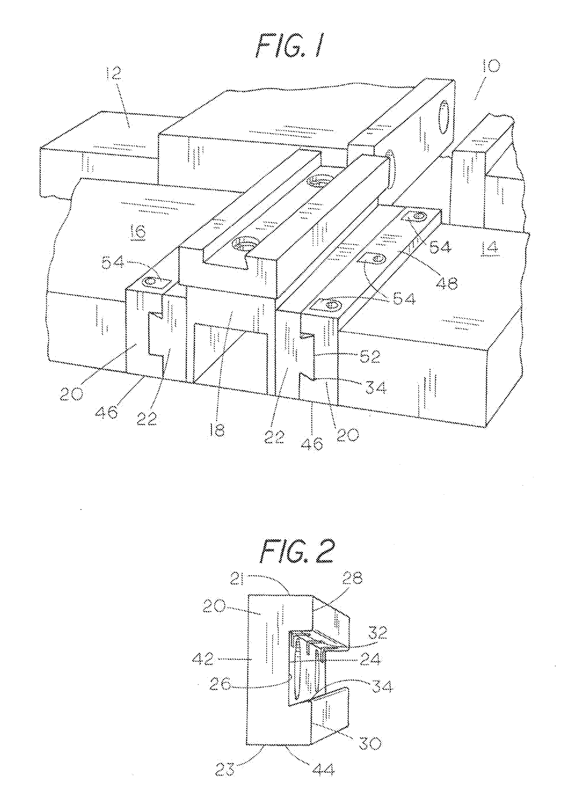
[0024]FIG. 1 shows the master jaw assembly 10 as used in a machinist's vise 12. The vise 12 is a standard vise with a fixed jaw 14 and a parallel movable jaw 16, in which the vise 12 is clamped together to hold a work piece 18. The master jaw assembly 10 includes a locking jaw 20 coupled to a detachable jaw 22. A locking jaw 20 is attached to both the fixed jaw 14 and the movable jaw 16 of the vise 12. A detachable jaw 22 is coupled to each locki...


PUM


Abstract

A master jaw assembly used in a vise including a locking jaw, a detachable jaw and a clamping device disposed in the locking jaw, securely clamping the detachable jaw to the locking jaw. The locking jaw has a groove extending along an inner surface of the locking jaw defined by a first and second edge. The second edge is tapered inward and downward toward the base. The detachable jaw has a dovetail protrusion along one side surface thereof. The clamping device includes a plurality of specially-shaped nuts having a downwardly tapered edge, said nuts designed to receive one end of a double-ended threaded stud. The detachable jaw becomes fixed to the locking jaw by inserting the protrusion into the groove and torquing the studs to tighten the nuts downward against the protrusion such that the protrusion is clamped between the taper of the second edge and the nuts.

Description

BACKGROUND OF THE INVENTION[0001]I. Field of the Invention[0002]This invention relates generally to an improvement in engineers' vises or the like, and more particularly to master jaw assemblies for the quick removal and attachment of hard and soft jaws.[0003]II. Discussion of the Prior Art[0004]An engineer's vise is used in metalworking applications. An engineer's vise, like a woodworking vise, is used to hold a work piece. Vises have one fixed jaw and another parallel jaw which is moved towards or away from the fixed jaw by a screw. In an engineer's vise, jaws are made either of hard or soft metal. Hard jaws are available with either a coarse gripping surface or are ground flat and smooth. Hard jaws can lead to deformation and error of the finished work piece if the vise is over-tightened, or if the operator is unskilled or negligent in his handling of the work piece around hard jaws. Soft jaws, in contrast, are usually made of a soft metal such as aluminum, plastic or wood. Soft ...

Claims


Application Information

Patent Timeline
IPC IPC(8): B25B1/24
CPCB25B1/2452B25B1/2405
Inventor EHNSTROM, WILLIAM J.
Owner BELLATEX INDS
Learn More