Strobe device and imaging device

a technology of imaging device and strobe, which is applied in the direction of lighting and heating apparatus, instruments, point-like light sources, etc., can solve the problem of further reducing the amount of ligh

Inactive Publication Date: 2012-10-11
PANASONIC CORP
View PDF2 Cites 1 Cited by
  • Summary
  • Abstract
  • Description
  • Claims
  • Application Information

AI Technical Summary

Benefits of technology

[0021]The structure discussed above allows the light from the discharge tube not to travel artlessly outside the irradiation range but to have both the main beam and the complementary beam fall efficiently within the irradiation range in front.

Problems solved by technology

However, this strobe device has a possibility that the amount of light further decreases because the light having undergone the reflections on the reflective lampshade is condensed with the optical member having a different refractive index (refer to, e.g. Patent Literature 1).

Method used


Image

  • Strobe device and imaging device
  • Strobe device and imaging device
  • Strobe device and imaging device

Examples


embodiment 1

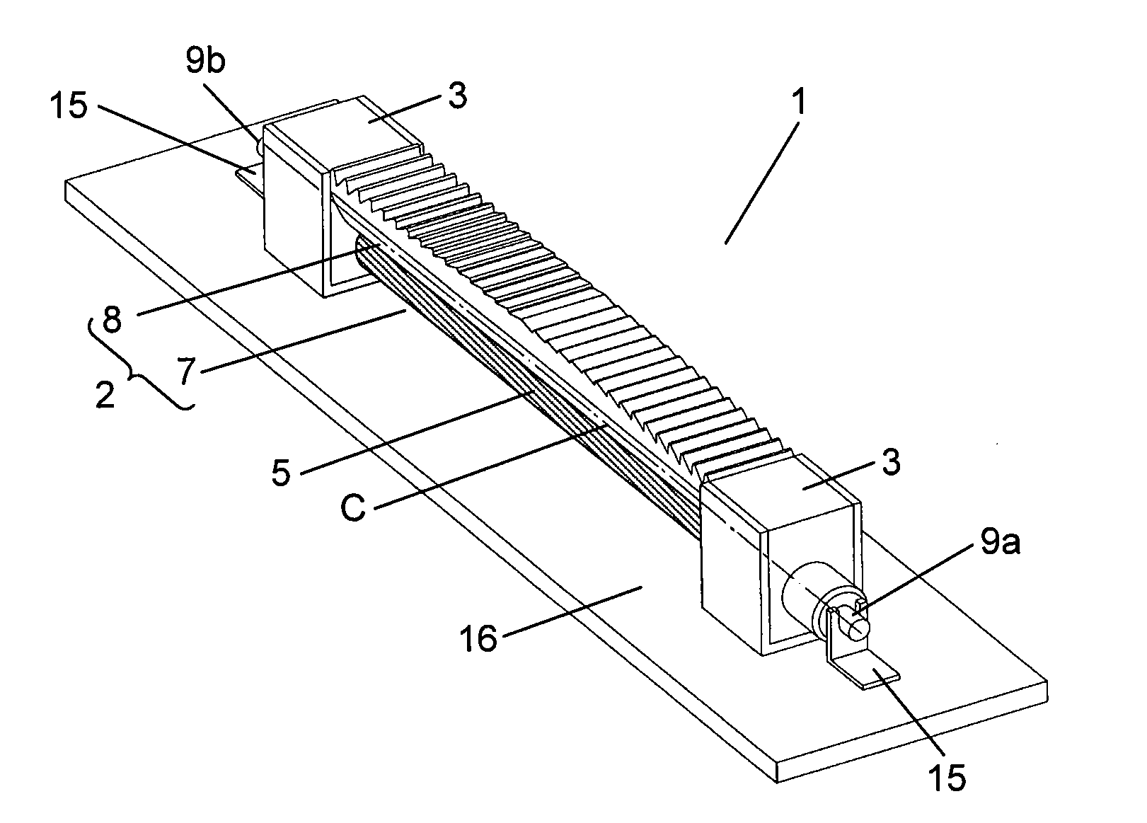
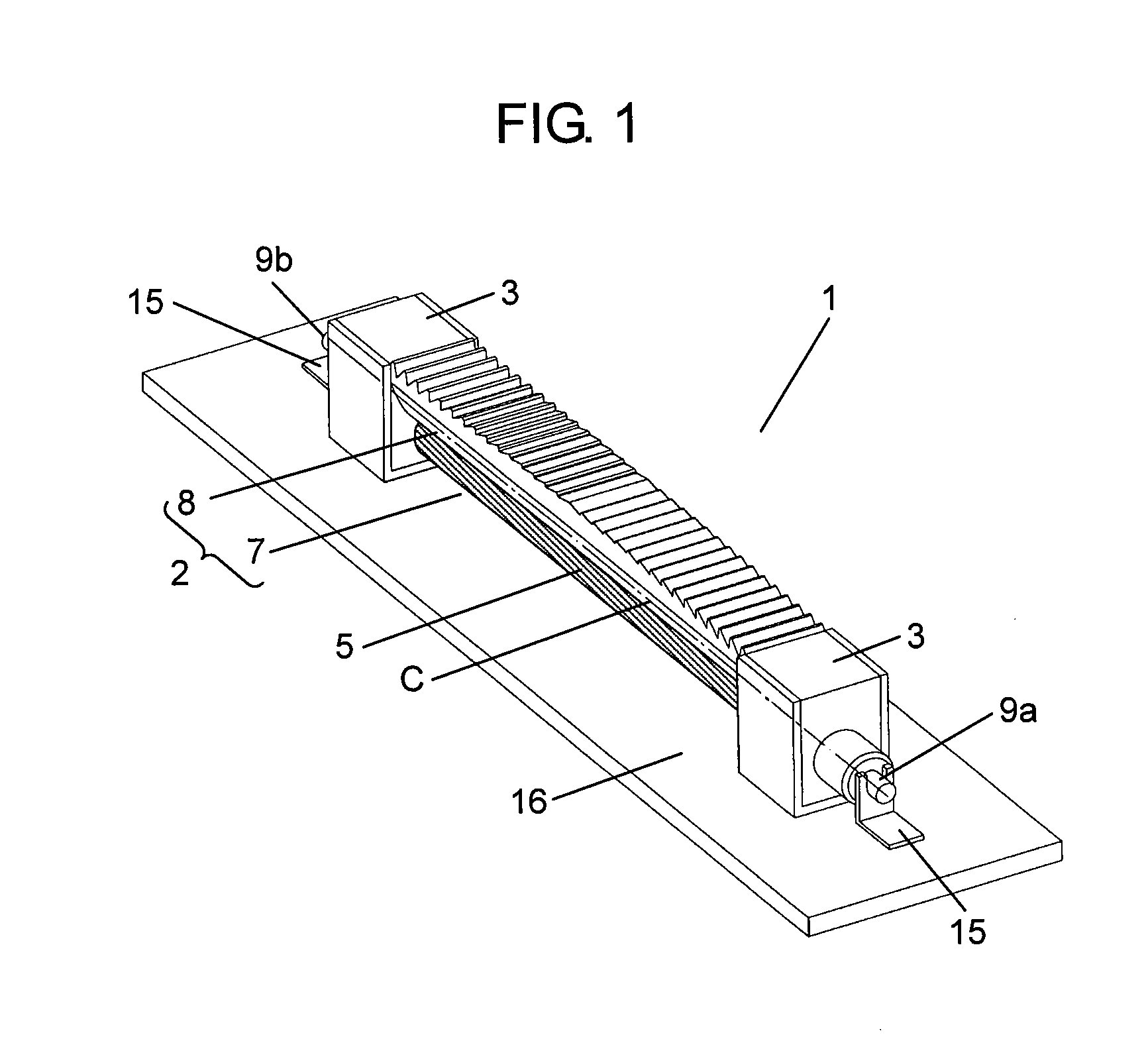
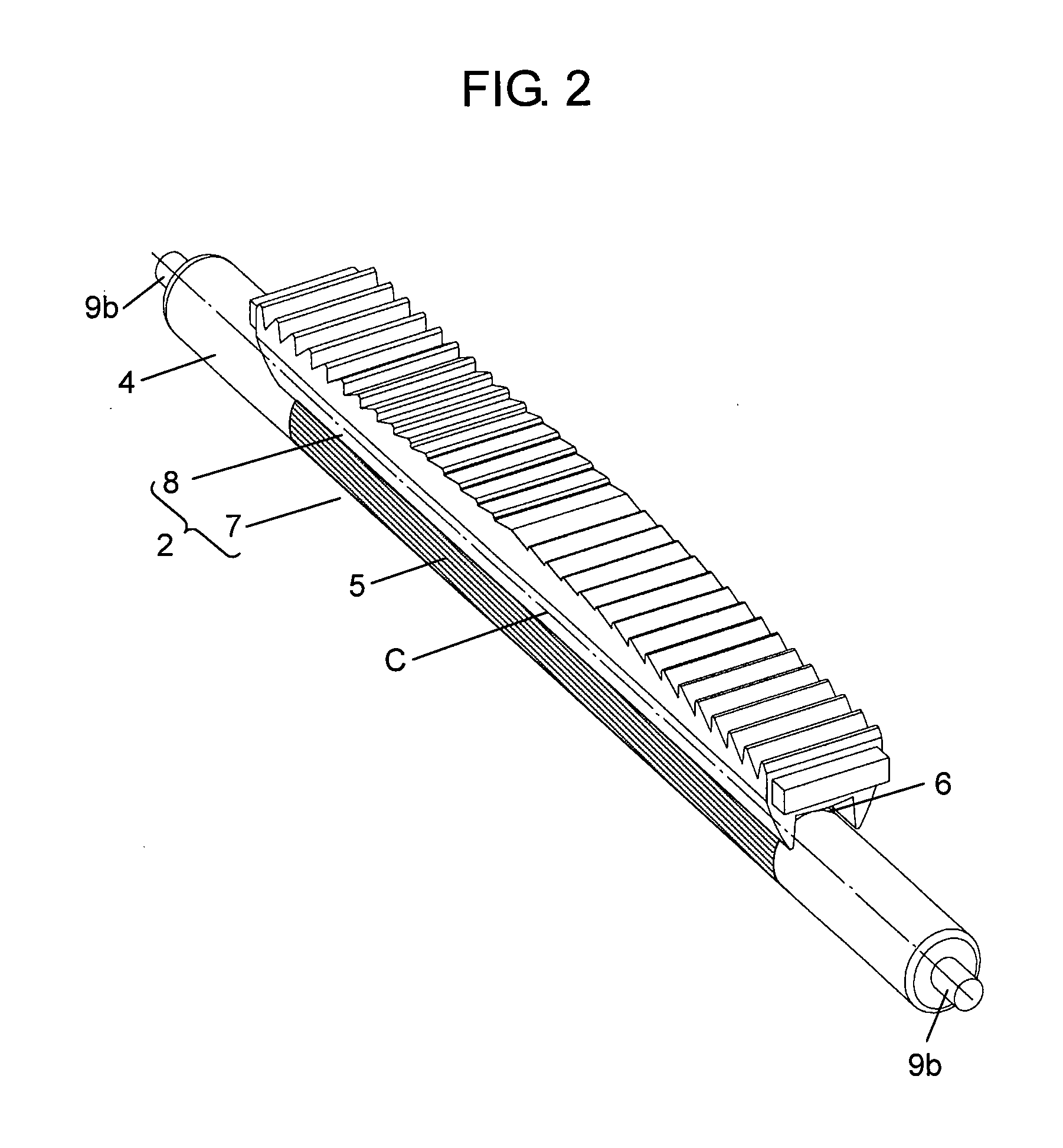
[0064]The inventors have acknowledged that the strobe device of the present invention performs well. To be more specific, as shown in FIG. 4A, strobe device 1 in accordance with this first embodiment is the one discussed in the previous exemplary embodiment. Discharge tube 7 employs a flash-discharge tube that is formed of glass bulb 4 having an outer diameter of 1.3 mm and an inner diameter of 0.85 mm. Reflective film 5 is formed on glass bulb 4 within a range of 250° with respect to center axis C of glass bulb 4, while light transparent section 6 is formed within a range of 110° with respect to center axis C. Optical member 8 is made of acrylic resin having refractive index of ca. 1.49 with respect to “d” line. A radiation angle of strobe device 1 in accordance with the first embodiment is set at 27° for each side with respect to optical axis BL (total range is 54°, which corresponds to 28 mm for 35 mm type lens).

[0065]A curvature radius of first incident face 10 is thus set at 3 ...

embodiment 2

[0081]The inventors also have acknowledged the performance of strobe device 1 having a wider radiation angle. To be more specific, strobe device 1 in accordance with the second embodiment of the present invention, as shown in FIG. 6C, has been demonstrated in the exemplary embodiment previously discussed. Discharge tube 7 employs a flash-discharge tube that is formed of glass bulb 4 having an outer diameter of 1.3 mm and an inner diameter of 0.85 mm. Reflective film 5 is formed on glass bulb 4 within a range of 250° with respect to center axis C of glass bulb 4, while light transparent section 6 is formed within a range of 110° with respect to center axis C. Optical member 8 is made of acrylic resin having refractive index of ca. 1.49 with respect to “d” line. A radiation angle of strobe device 1 in accordance with the second embodiment is set at 30° for each side with respect to optical axis BL (total range is 60°, which corresponds to 24 mm for 35 mm type lens).

[0082]A curvature r...


PUM


Abstract

A strobe device includes a discharge tube having a light transparent section and an optical member disposed in front of the light transparent section. The optical member includes a first incident face receiving a main beam radiated forward from the light transparent section, a pair of second incident faces receiving a complementary beam radiated forward and obliquely from the light transparent section, a pair of total reflection faces for reflecting totally and forwardly the complementary beam coming from the second incident faces, and an beam-emitting face through which the main beam and the complementary beam go outward. Each of the pair of total reflection faces is formed of a curved face such that the space between the curved faces expands toward the front side from the discharge tube side between the total reflection faces expanding, and two tangential lines to the curved faces at starting points located on the discharge tube side cross each other at an intersection point behind the center of the discharge tube and yet in front of the outer peripheral face of the glass tube.

Description

TECHNICAL FIELD[0001]The present invention relates to a strobe device formed of a discharge tube and an optical member. The discharge tube includes a glass bulb having a reflective film formed on an outer face thereof and a light transparent section formed on a front face, where no reflective film is formed, of the glass bulb. The optical member radiates light supplied through the light transparent section of the discharge tube to a photographic object. The present invention also relates to an imaging device equipped with the same strobe device.BACKGROUND ART[0002]A conventional strobe device to be used for shooting a still picture or a moving picture includes a reflective lampshade (reflector) for reflecting light, radiated from a discharge tube, toward an object. The light radiated from the center of the discharge tube (glass bulb) travels in every direction (radiated from the entire circular direction of the discharge tube), so that an opening of the reflective lampshade should b...

Claims


Application Information

Patent Timeline
Patent Type & Authority Applications(United States)
IPC IPC(8): G03B15/02F21Y101/00
CPCG03B15/02G03B2215/0582G03B2215/0592G03B15/05
Inventor MURAI, TOSHIAKI
Owner PANASONIC CORP
Why Eureka
Try Eureka