Unlock instant, AI-driven research and patent intelligence for your innovation.

Fuel cell system

a fuel cell and system technology, applied in the field of fuel cell systems, can solve the problems of water flowing upward along the pressing surface, the open/close valve may not open and close smoothly, so as to reduce the size in the vertical direction of the portion including the fluid control valve and the pipes, reduce pressure loss, and easy installation

Active Publication Date: 2016-12-20
TOYOTA JIDOSHA KK
View PDF13 Cites 0 Cited by
  • Summary
  • Abstract
  • Description
  • Claims
  • Application Information

AI Technical Summary

Benefits of technology

The present invention provides a fuel cell system with a fluid control valve that can prevent water from remaining on the pressing surfaces and can effectively cause the water to fall along the pressing surfaces due to the effect of flowing gas and gravity. This results in a smooth opening and closing of the valve even in a low-temperature environment. The system also includes an outlet shutoff valve that can prevent water from freezing in the peripheral region of the pressing surfaces, and a valve member and valve seat with pressing surfaces that are tilted relative to the gravity-acting direction. The system can be easily installed on an automotive vehicle or the like, and can reduce pressure loss of the gas flowing in the gas flow path.

Problems solved by technology

If the remaining water freezes at or below the freezing point, the open / close valve may fail to open and close smoothly.
If the water freezes, the open / close valve may fail to open and close smoothly.
When the pressing surface of the valve seat is tilted, the flow of gas in operation may cause water to flow upward along the pressing surface.
Therefore, when the fuel cell system is in operation, the tilted configuration of the valve seat may fail to be effectively used to remove the water from the pressing surface of the valve seat and may not be able to prevent freezing of the remaining water.
Thus, the valve may fail to open and close smoothly in a low-temperature environment.

Method used


Image

  • Fuel cell system
  • Fuel cell system
  • Fuel cell system

Examples


Embodiment Construction

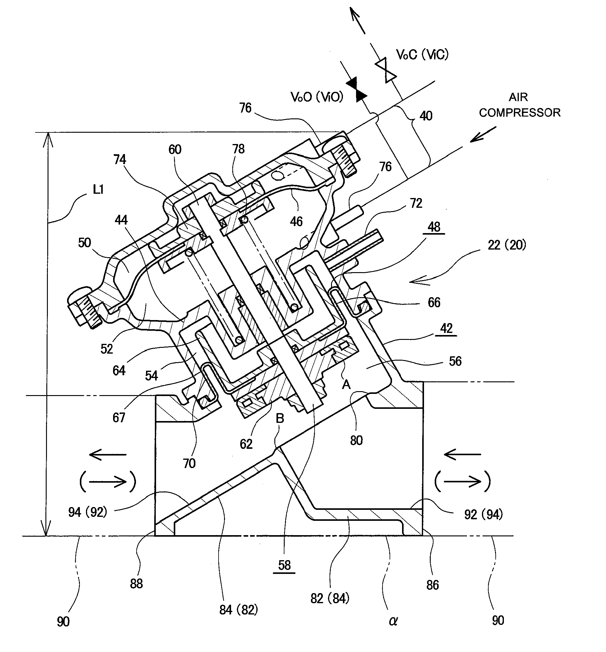
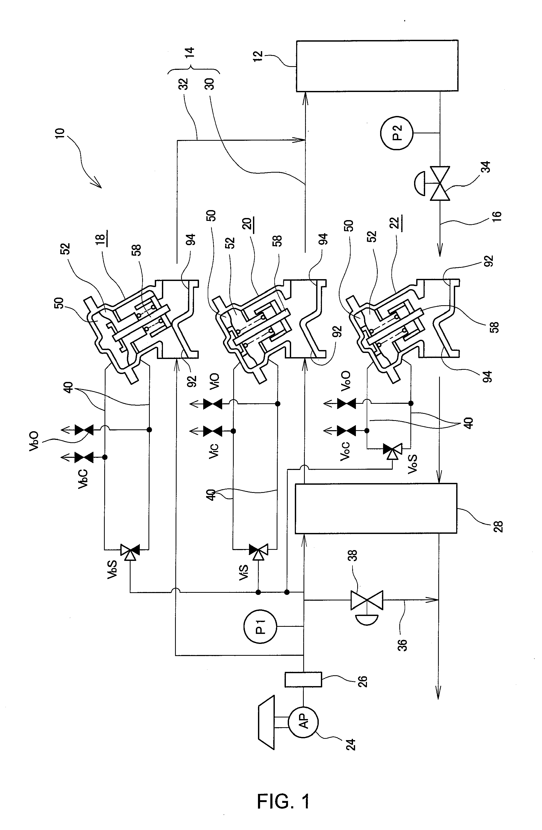
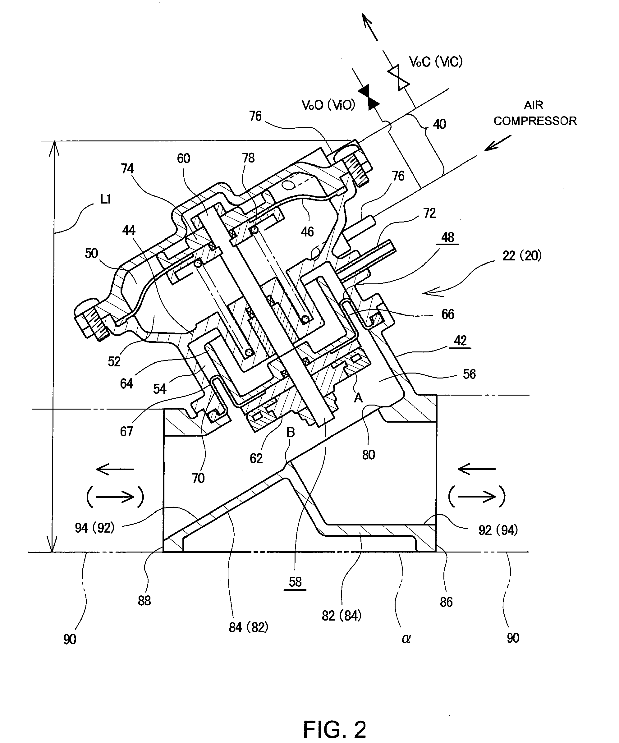
[0028]An example according to an embodiment of the present invention is described with reference to the drawings. FIGS. 1 and 2 illustrate the embodiment of the present invention. FIG. 1 illustrates a schematic configuration of a fuel cell system according to the present embodiment. A fuel cell system 10 includes a fuel cell stack 12, an oxidizing gas supply flow path 14 and an oxidizing related gas discharge flow path 16, a humidifier bypass valve 18, an inlet shutoff valve 20, and an outlet shutoff valve 22.

[0029]The fuel cell stack 12 generates electricity through an electrochemical reaction between oxygen and hydrogen. More specifically, the hydrogen gas serving as a fuel gas and the air serving as an oxidizing gas are supplied to the fuel cell stack 12. Electrical energy can be obtained by a plurality of fuel cells (not illustrated) in the fuel cell stack 12, through the electrochemical reaction between oxygen and hydrogen. The fuel cell includes, for example, a film-electrode ...


PUM

PropertyMeasurementUnit
angleaaaaaaaaaa
angleaaaaaaaaaa
displacementaaaaaaaaaa

Abstract

An outlet shutoff valve where pressing surfaces, which press against each other, of a valve member and a valve seat are tilted relative to the vertical direction and where a drive shaft can be driven in a direction tilted relative to the vertical direction. In the outlet shutoff valve, the pressing surfaces are set high on the upstream side of gas flowing in a flow-path-forming pressure chamber, where the gas flows, and low on the downstream side.

Description

[0001]This is a 371 national phase application of PCT / JP2007 / 072040 filed 7 Nov. 2007, claiming priority to Japanese Patent Application No. JP 2006-330736 filed 7 Dec. 2006, the contents of which are incorporated herein by reference.TECHNICAL FIELD[0002]The present invention relates to a fuel cell system including a fuel cell that generates electricity through an electrochemical reaction between an oxidizing gas and a fuel gas, and a fluid control valve that closes or opens a gas flow path according to a displacement in an axial direction of a valve member having a drive shaft.TECHNICAL BACKGROUND[0003]A fuel cell system includes a fuel cell that generates electricity through an electrochemical reaction between a fuel gas and an oxidizing gas (reaction gases), a gas-supplying flow path that supplies the reaction gases to the fuel cell, and a gas-discharging flow path that discharges the reaction gases from the fuel cell. Open / close valves for the fuel cell, corresponding to the flui...

Claims


Application Information

Patent Timeline
Patent Type & Authority Patents(United States)
IPC IPC(8): H01M8/04089H01M2/00F16K31/126H01M8/04
CPCF16K31/1262H01M8/04089Y02E60/50
Inventor TAKESHITA, MASAHIRO
Owner TOYOTA JIDOSHA KK