Feeding device

A feeding device and feeding technology, applied in the direction of packaging, transportation, packaging, containers, etc., can solve the problems of high labor intensity, affecting the accuracy of blanking, and hindering materials, etc., and achieve good arch breaking effect, good arch breaking strength, The effect of flipping smoothly

Active Publication Date: 2016-06-01
ZHUHAI YOUTE SMART KITCHEN TECH CO LTD
View PDF8 Cites 10 Cited by
  • Summary
  • Abstract
  • Description
  • Claims
  • Application Information

AI Technical Summary

Problems solved by technology

The material of the above-mentioned solid seasoning in the solid seasoning injector falls by its own weight, but if the fluidity of the material is poor or the material is wet, during the feeding process, the material is easy to fall in the conical funnel of the storage container above the screw rod. The bottom of the structure forms a compacted arch bridge, which prevents the material from entering the screw in the feeding chamber, affects the normal operation of the blanking operation, and affects the accuracy of the blanking
[0005] In the prior art, the methods used to solve the arch erection are mostly manual breaking or mechanical breaking of the arch, the efficiency of manual breaking is low, and the labor intensity is high
Mechanical arch breaking generally adopts the installation of agitator at the bottom of the silo as the mechanical arch breaking equipment, but the agitator in the existing feeder can only be limited to the partial arch breaking at the bottom of the silo, but it cannot be used near the mouth of the silo. Therefore, there will also be a problem that the material will form an arch bridge near the position above the silo mouth, so that there is no material to go down at the receiving part of the screw.

Method used


Image

  • Feeding device
  • Feeding device
  • Feeding device

Examples


Embodiment Construction

[0034] The present invention is described in detail through the following embodiments. However, those skilled in the art should understand that the following embodiments do not limit the protection scope of the present invention, and any improvements and changes made on the basis of the present invention are within the protection scope of the present invention.

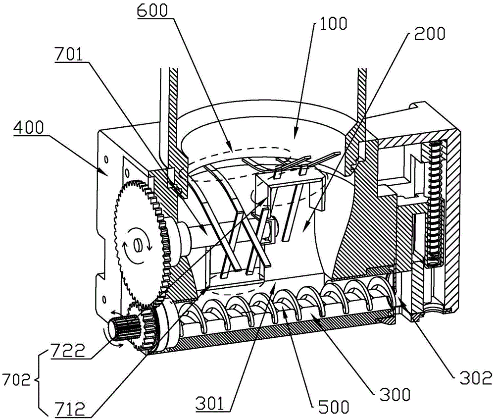
[0035] See attached figure 1 , the present invention discloses a feeding device, comprising a feed port 100, a stirring chamber 200 and a feeding chamber 300, wherein the feed port 100, the stirring chamber 200 and the feeding chamber 300 communicate with each other, wherein the stirring chamber 200 and The feeding chamber 300 is surrounded by the shell 400 . Specifically, the feeding port 100 is disposed above the stirring chamber 200 , and the feeding chamber 300 is disposed below the stirring chamber 200 . The upper part of the feeding port 100 can be used to cooperate with the storage container. Generally, the ...


PUM


Abstract

The invention provides a feeding device. The feeding device comprises a feeding inlet, a stirring cavity and a feeding cavity, wherein the stirring cavity is arranged between the feeding inlet and the feeding cavity; a feeding threaded rod penetrates through the feeding cavity; an arc breaking elastic piece is arranged in the stirring cavity, one end of the arc breaking elastic piece is fixedly installed in the combination position of the stirring cavity and the feeding inlet, and the other end of the arc breaking elastic piece is suspended; a stirring mechanism matched with the arc breaking elastic piece is further arranged in the stirring cavity and comprises a rotary shaft and a stirring paddle; in the rotation process of the stirring mechanism, the stirring paddle periodically makes contact with the arc breaking elastic piece, and the contact position of the arc breaking elastic piece deforms elastically, so that the suspended end of the arc breaking elastic piece is driven to swing, and arc breaking is carried out on materials; when the stirring paddle and the arc breaking elastic piece are separated, the arc breaking elastic piece recovers the natural state. According to the feeding device, the arc breaking elastic piece is triggered by the stirring mechanism to swing vertically, arc breaking is carried out on the materials within a large range, the effect that the feeding threaded rod receives materials uniformly is guaranteed, and the discharging precision is effectively improved.

Description

technical field [0001] The invention relates to a solid material extruding device, in particular to a feeding device for breaking material arching. Background technique [0002] In life, it is often necessary to prepare various materials, such as seasoning preparation, drug preparation, chemical raw material preparation, etc. For the conveying and quantification of solid materials, one of the common techniques is quantitative feeding through screws. At present, screw conveying technology is already a relatively mature general technical means for conveying powdery or granular solids. Especially in the field of solid seasoning equipment for kitchens, screw conveying technology is also widely used, which is mainly used for quantitatively transporting granular solid seasonings such as salt, sugar, and monosodium glutamate. [0003] In the traditional feeder for powder or granular materials, the feeder has only one screw as the propeller, and in the actual application process, ...

Claims


Application Information

Patent Timeline
Patent Type & Authority Applications(China)
IPC IPC(8): B65D88/68
CPCB65D88/68
Inventor 苏波李东星张兵王峰
Owner ZHUHAI YOUTE SMART KITCHEN TECH CO LTD
Why Eureka
Try Eureka