Sleeve type continuous calcining vertical kiln

A sleeve type and calcining technology, applied in the field of high temperature calcination production, can solve the problems such as the inability to continuously produce lime kilns, reduce the production efficiency of lime kilns, and affect product quality, etc., and achieve the effects of good energy saving, simple structure and convenient control.

Active Publication Date: 2011-11-02
ZHEJIANG DEYAO ENERGY SAVING TECH CO LTD
View PDF8 Cites 11 Cited by
  • Summary
  • Abstract
  • Description
  • Claims
  • Application Information

AI Technical Summary

Problems solved by technology

Compared with the shell kiln of Beckenbach, the structure of this vertical continuous calcining lime kiln has been greatly simplified, but this vertical continuous calcining lime kiln can only process blocky stone with large shape and volume, while for small powder Shaped or granular stone, it cannot be calcined, otherwise the powdery stone will enter the hot air outlet channel from the air inlet and outlet on the hot air outlet channel due to the influence of the combustion airflow injected from the crater, resulting in a lot of waste of raw materials, and , in the process of calcining lime, if the combustion airflow injected from the crater is too large, it will easily cause air resistance to block the falling of raw materials, so that the continuous production of the lime kiln will not be possible, and the production efficiency of the lime kiln will be reduced. Some raw materials close to the outer wall of the hot air inlet and outlet channel are burned, which affects product quality

Method used


Image

  • Sleeve type continuous calcining vertical kiln
  • Sleeve type continuous calcining vertical kiln

Examples


Embodiment Construction

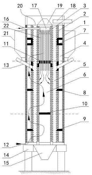
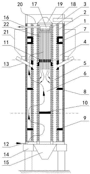
[0015] The specific embodiment of sleeve type continuous calcination shaft kiln of the present invention is as figure 1 As shown, the direction of the arrow in the figure is the airflow direction. The kiln body of the shaft kiln is mainly composed of a cylindrical furnace shell 1 made of thermal insulation material installed on the base 14 and an outer cylinder 2 and an inner cylinder 3 coaxially sleeved in the furnace shell 1 and made of refractory materials. , the inner cylinder 3, the outer cylinder 2 and the furnace shell 1 together form a three-layer sleeve kiln structure, wherein the inner cylinder 3 and the outer cylinder 2 are mainly composed of refractory bricks layer by layer, and the inner cavity of the inner cylinder 3 An axially extending hollow pipe 6 is formed, an axially extending annular furnace chamber 5 is formed between the inner cylinder 3 and the outer cylinder 2, and an axially extending annular periphery is formed between the furnace shell 1 and the out...


PUM


Abstract

The invention discloses a sleeve type continuous calcining vertical kiln. An annular kiln cavity is formed by the encircling of an inner barrel and an outer barrel which are sleeved together in a kiln body; the annular kiln cavity is provided with a preheating area, a calcining area and a cooling area in sequence from top to bottom; the barrel wall of the inner barrel is provided with a pluralityof ventilation holes for communicating the annular kiln cavity with the inner cavity of the inner barrel; the periphery of the outer barrel is covered with a barrel-shaped kiln shell; a peripheral air channel is arranged between the inner wall face of the barrel-shaped kiln shell and the outer wall face of the outer barrel in an encircling manner; ventilation holes for communicating the annular kiln cavity with the peripheral air channel are distributed on the barrel wall of the outer barrel; radial isolation structures are distributed at intervals in the inner cavity of the inner barrel and the periphery air channel in a staggered way along the axial direction of the kiln body; and a fuel feeding device communicated with the calcining area in the annular kiln cavity is arranged on the upper part of the kiln shell. The vertical kiln has a simple structure and a good energy-saving effect; and calcination of powdery or particulate small-diameter stone raw materials is realized, waste ofraw materials is avoided, meanwhile, the operation of the kiln is simplified, and the fuel consumption is lowered.

Description

technical field [0001] The invention belongs to the technical field of high-temperature calcination production of materials such as lime and metal magnesium, and specifically relates to a vertical calcination kiln. Background technique [0002] With the development of the metallurgical industry and the continuous improvement of calcination technology and process, my country has put forward higher requirements for the quality of magnesium metal and lime, the main slagging agent in steelmaking production. Existing calcining kilns mainly include earthen kiln, rotary kiln and shaft kiln. The earth kiln has low production efficiency and heavy pollution. The lime produced by it has high impurity content and low activity. Its products are mainly used in the construction field and have been banned for use at present. The rotary kiln equipment is large in size, occupies a large area, and consumes energy. higher. Shaft kilns are also called shaft kilns. In the 1980s, shaft kilns wer...

Claims


Application Information

Patent Timeline
Patent Type & Authority Applications(China)
IPC IPC(8): F27B1/02F27B1/10F27B1/14F27B1/16F27B1/20F27B1/21F27B1/22
Inventor 唐德顺孙振华郭向东王伟亮
Owner ZHEJIANG DEYAO ENERGY SAVING TECH CO LTD
Why Eureka
Try Eureka