Antenna and the method for adjusting the operation bandwidth thereof

Inactive Publication Date: 2012-10-04
ARCADYAN
View PDF12 Cites 0 Cited by
  • Summary
  • Abstract
  • Description
  • Claims
  • Application Information

AI Technical Summary

Benefits of technology

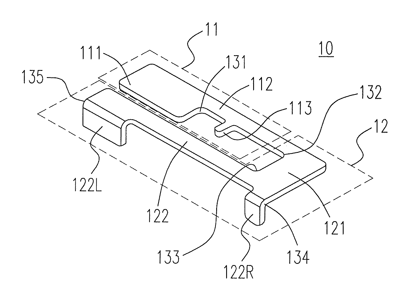
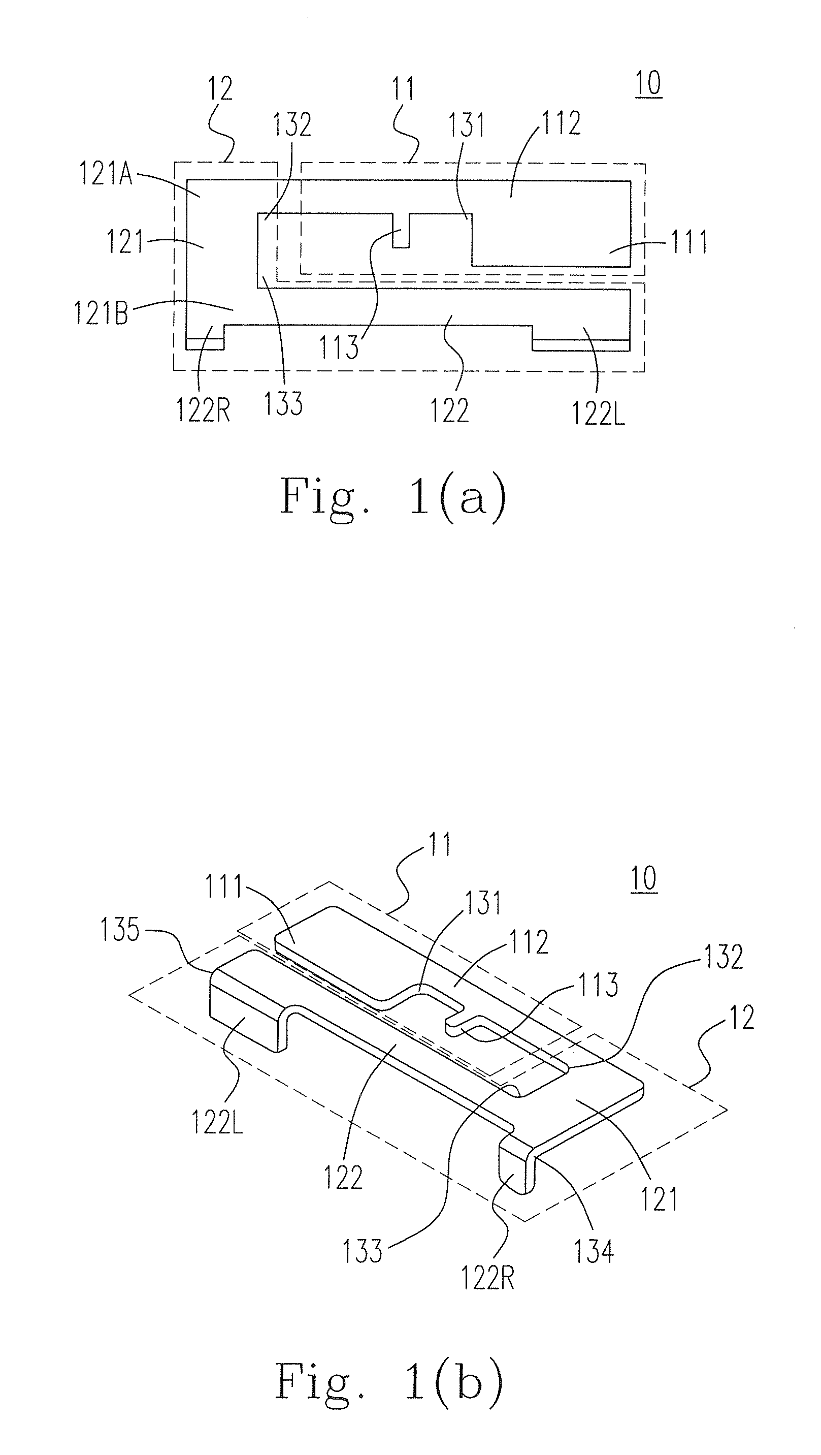
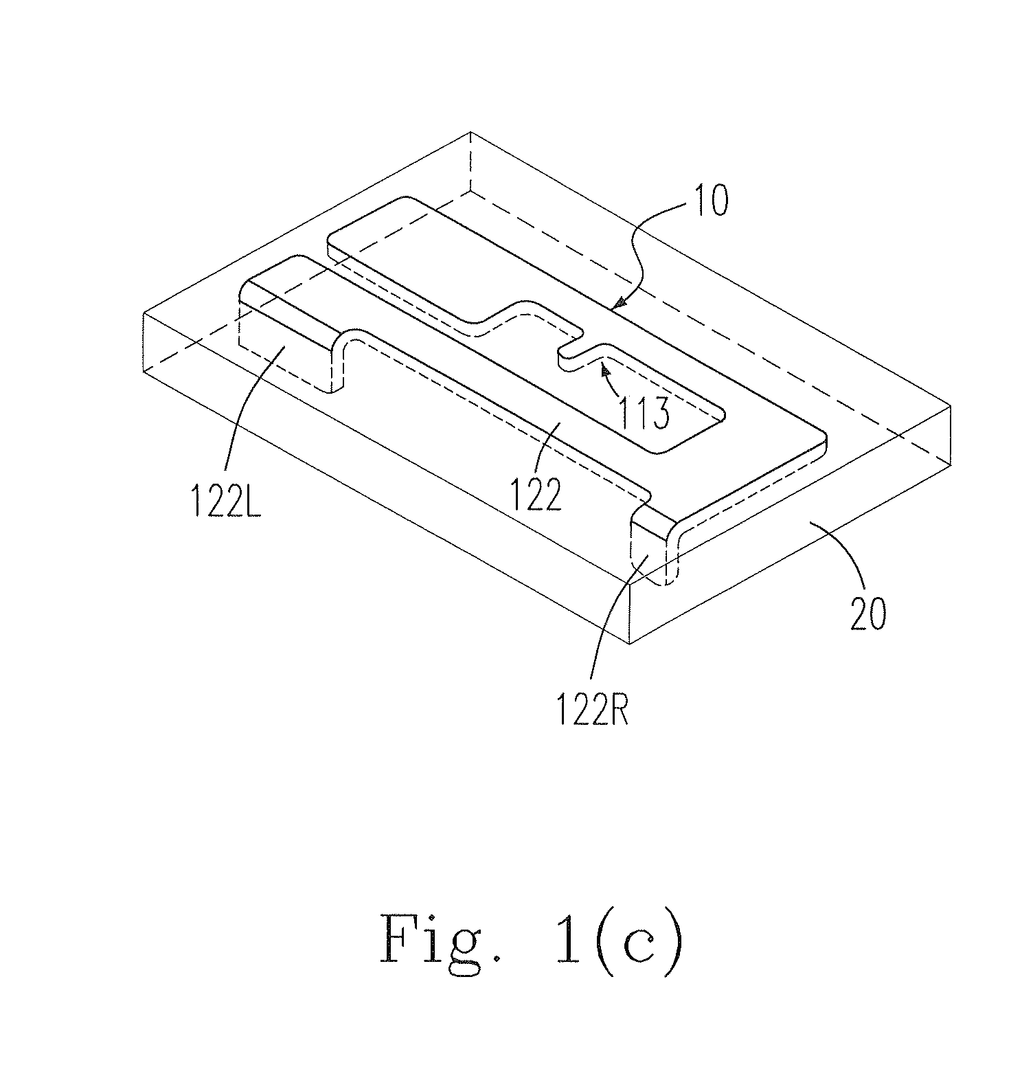
[0006]In accordance with an aspect of the present invention, an antenna and the method for adjusting the operation bandwidth thereof are provided. The present invention can easily adjust the antenna to achieve a suitable operation frequency, and can adjust an operation bandwidth of the antenna. The antenna of the present invention is connected to an interface connection port of an electronic device. The antenna includes a radiation element and a ground, element. The radiation element includes a first adjusting portion, a second adjusting portion and a signal feeding terminal. The ground element includes a ground portion and a third adjusting portion. The ground element extends from the radiation element, and a first included angle is formed between the first adjusting portion and the second adjusting portion. The second adjusting portion extends from the first adjusting portion, and a second included angle is formed between the second adjusting portion and the third adjusting portion. A first end of the third adjusting portion extends from the second adjusting portion, and a third included angle is formed between the third adjusting portion and the ground portion. The ground portion extends from a second end of the third adjusting portion, and the first adjusting portion is disposed between the second adjusting portion and the ground portion.
[0009]The present invention provides an antenna and the method of adjusting the operation frequency thereof. The antenna is applicable to various kinds of wireless communication devices, and can be easily adjusted and modified according to the demand of the product to achieve the suitable frequency band application. Since the bandwidth of the antenna of the present invention is wider than those of other PIFAs, even if the antenna of the present invention is used under different environments, the frequency band thereof still efficiently falls within the operation frequency band. This efficiently saves the cost of manufacturing multiple molds. Besides, the antenna of the present invention is applicable to various kinds of wireless network devices, e.g. the notebook computer, the mobile phone, etc.

Problems solved by technology

This will greatly influence the manufacturing process of the PIFA, i.e. greatly increasing the cost of the mold.

Method used


Image

  • Antenna and the method for adjusting the operation bandwidth thereof
  • Antenna and the method for adjusting the operation bandwidth thereof
  • Antenna and the method for adjusting the operation bandwidth thereof

Examples


embodiment 1

2. The method of Embodiment 1, wherein the radiation element, further comprises a signal feeding terminal, the first adjusting portion has an edge, and the length of the radiation element is a sum of the total width and a first length from the signal feeding terminal to the edge of the first adjusting portion.

3. The method of any one of Embodiments 1-2, wherein the operation frequency is 2.45 GHz.

4. The method of any one of Embodiments 1-3, further comprising a step of:

[0044]setting a ratio of the second width to the first width to be 35 to enable the operation bandwidth to, be 640 MHz.

5. The method of any one of Embodiments 1-4, wherein a ratio of the second width to the sum is between 0.5 and 1.

6. The method of any one of Embodiments 1-5, wherein the ratio is 0.972.

7. A method for adjusting an operation bandwidth of an antenna, wherein the antenna includes a radiation element, and the radiation element includes a first adjusting portion having a first width and a second adjusting ...

embodiment 7

8. The method of Embodiment 7, wherein the radiation element further comprises a signal feeding terminal, the first adjusting portion has an edge, and the radiation element has a length being a sum of the total width and a first length from the signal feeding terminal to the edge of the first adjusting portion.

9. The method of any one of Embodiments 7-8, wherein the operation frequency is 2.45 GHz.

10. The method of any one of Embodiments 7-9, further comprising a step of:

[0047]setting a ratio of the second width to the first width to be 35 to enable the operation bandwidth to be 640 MHz.

11. The method, of any one of Embodiments 7-10, wherein a ratio of the second width to the sum is between 0.5 and 1.

12. The method of any one of Embodiments 7-11, wherein the ratio is 0.972.

13. An antenna having an operation frequency and an adjustable operation bandwidth, comprising:

[0048]a radiation element including:[0049]a first adjusting portion having a first width; and[0050]a second adjusting ...

embodiment 13

14. The antenna of Embodiment 13, wherein a ratio of the second width to the first width is 35.

15. The antenna of any one of Embodiments 13-14, wherein the radiation element further comprises a signal feeding terminal, the first, adjusting portion has an edge, and the radiation element has a length being a sum of the total width and a first length from the signal feeding terminal to the edge of the first adjusting portion.

16. The antenna of any one of Embodiments 13-15, wherein the operation frequency is 2.45 GHz.

17. The antenna of any one of Embodiments 13-16, wherein a ratio of the second width to the first width is 35.

18. The antenna of any one of Embodiments 13-17, wherein a ratio of the second width to the sum is between 0.5 and 1.

19. The antenna of any one of Embodiments 13-18, wherein the ratio is 0.972.


PUM

PropertyMeasurementUnit
Frequencyaaaaaaaaaa
Frequencyaaaaaaaaaa
Lengthaaaaaaaaaa

Abstract

A method for adjusting an operation bandwidth of an antenna is provided. The antenna includes a radiation element, and the radiation element includes a first adjusting portion having a first width and a second adjusting portion having a second width. The method includes steps of seeking an operation frequency of the antenna; and adjusting the operation bandwidth of the antenna by adjusting the second width based on the operation frequency.

Description

CROSS-REFERENCE TO RELATED APPLICATION AND CLAIM OF PRIORITY[0001]The application claims the benefit of Taiwan Patent Application. NO. 10011698, filed on Apr. 1, 2011, in the Taiwan Intellectual Property Office, the disclosures of which are incorporated herein in their entirety by reference.FIELD OF THE INVENTION[0002]The present invention relates to an antenna and the method for adjusting the operation bandwidth thereof, especially relating to an antenna design for broadening the bandwidth of the antenna.BACKGROUND OF THE INVENTION[0003]Currently, various kinds of small-sized antennas are developed, to be applied to various kinds of hand-held electronic devices (e.g. the mobile phone or the notebook computer) or to the wireless transmission device (e.g. the AP). For example, the planar inverse-F antenna (PIFA) that has a light structure as well, as a good transmission efficiency and can be easily disposed on the inner wall of the hand-held electronic device, has, been widely used f...

Claims


Application Information

Patent Timeline
IPC IPC(8): H01Q1/24H01P11/00H01Q5/10
CPCY10T29/49016H01Q9/0421
Inventor HUANG, CHIH-YUNGLO, KUO-CHANG
Owner ARCADYAN
Why Eureka
Try Eureka