Case cover structure for fall prevention

a technology for preventing falls and coverings, applied in door/window fittings, building components, constructions, etc., can solve problems such as affecting the safety of maintenance workers during maintenance, and achieve the effects of enhancing convenience for maintenance and security, and preventing the cover from falling

Inactive Publication Date: 2011-08-25
ELEDYNA TECH CORP
View PDF4 Cites 1 Cited by
  • Summary
  • Abstract
  • Description
  • Claims
  • Application Information

AI Technical Summary

Benefits of technology

[0012]1. The adsorption element adsorbs and fixes the adsorbed element so that the cover is fixed on one side of the main frame, thereby preventing the cover from falling. Comparing with conventional automatic door, the present invention has more sorption between the cover and the main frame.
[0013]2. When the cover is in the second position, the protruding portion of the cover abuts against the top wall opposite to the revolving groove, one end of the cover abuts against the supporting portion and the vertical height of the other end of the cover is slightly higher than the supporting portion, so that the cover is fixed on one side of the main frame, thereby preventing the cover from falling and enhancing convenience for maintenance and security.
[0014]3. When the cover is in the second position, the protruding portion of the cover abuts against the protruding rib, so that the cover is fixed on one side of the main frame, thereby preventing the cover from falling and enhancing convenience for maintenance and security.

Problems solved by technology

Since no fixing structure is fixed on the cover 2a, maintenance workers must hold the cover 2a so that it is quite inconvenient for disassembling or assembling the cover 2a, and further, the falling of the cover 2a endangers the safety of maintenance workers during maintenance.

Method used


Image

  • Case cover structure for fall prevention
  • Case cover structure for fall prevention
  • Case cover structure for fall prevention

Examples


Embodiment Construction

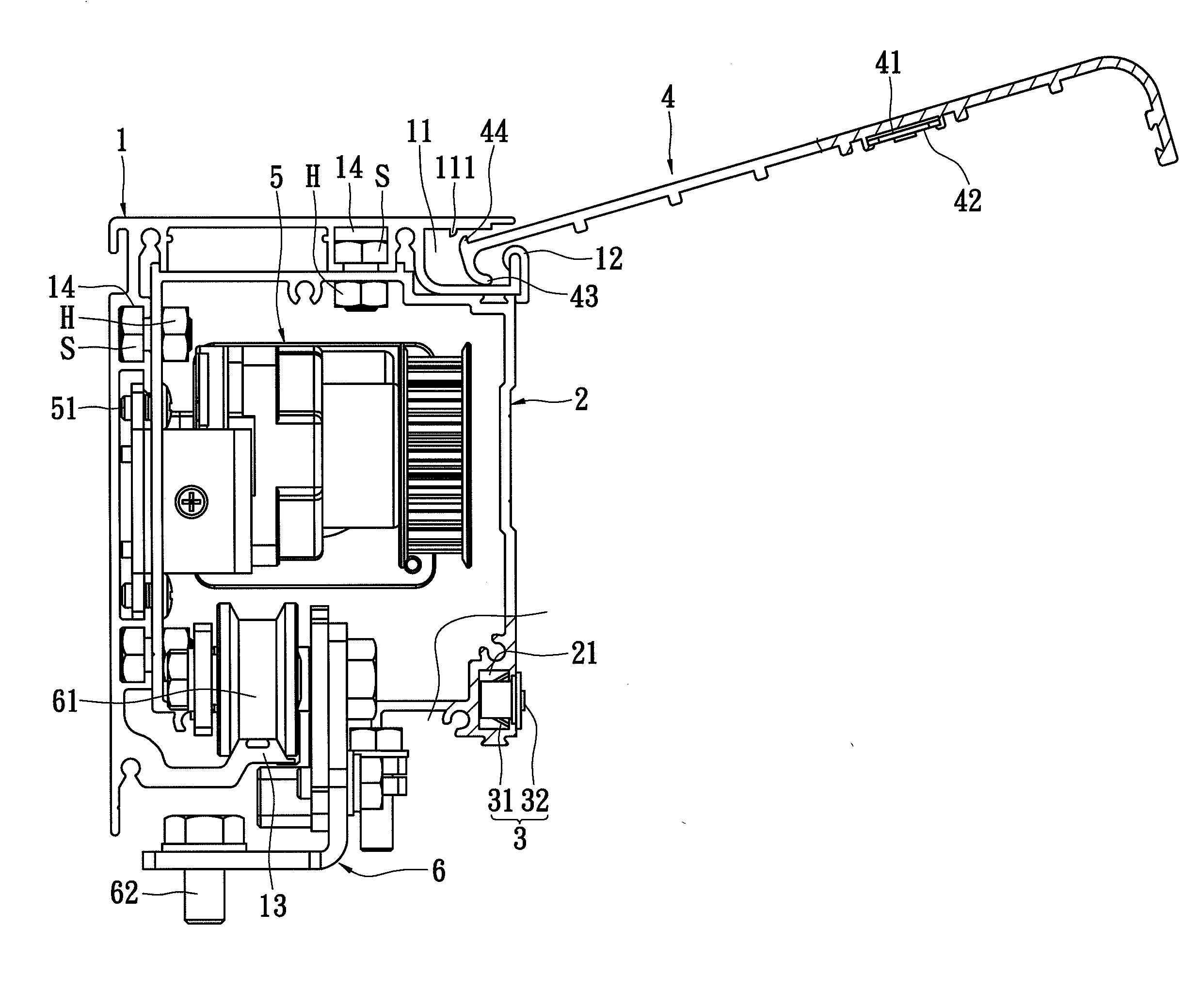
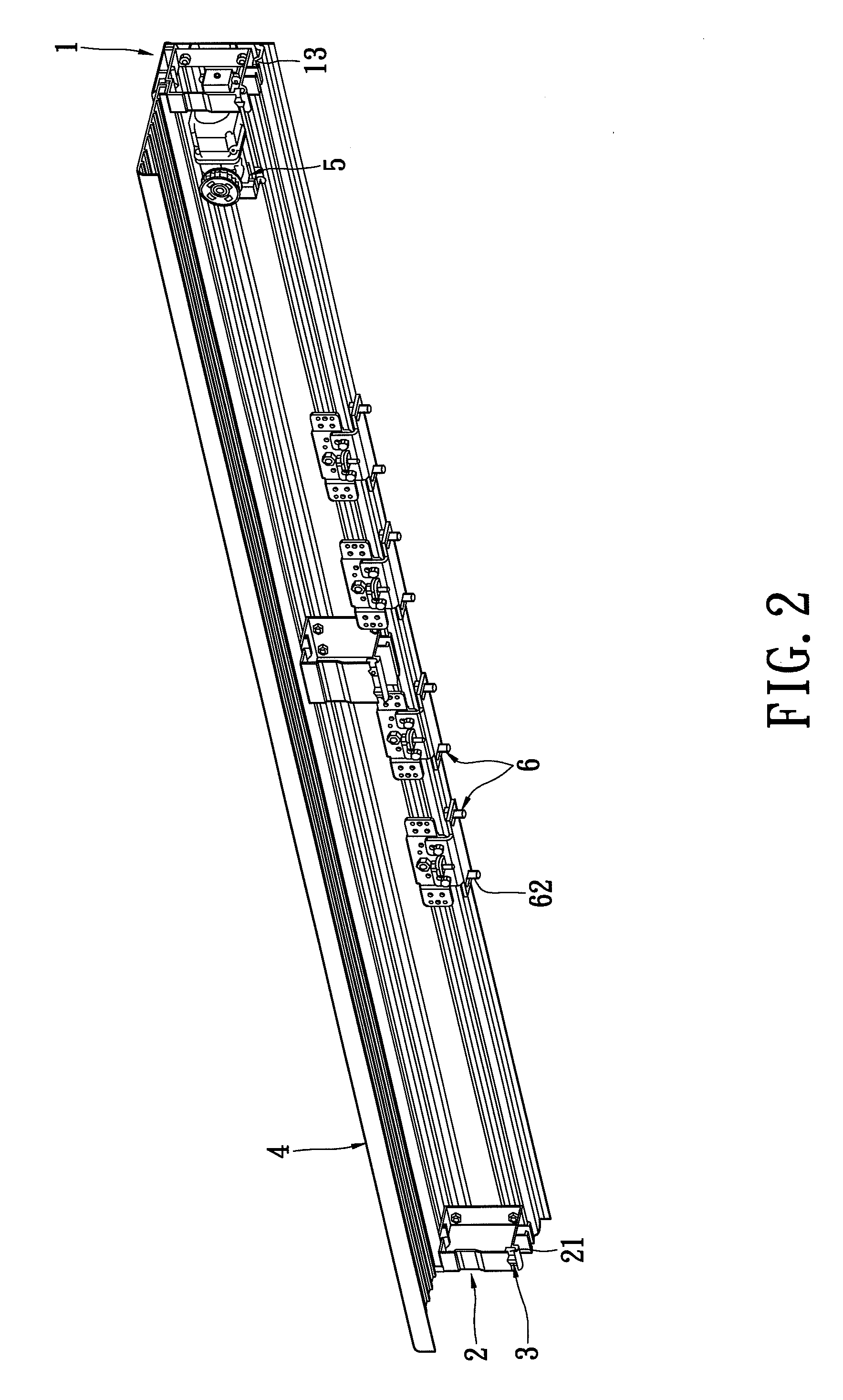
[0023]Please refer to FIGS. 2-8 illustrating a case cover structure for fall prevention according to the present invention, which is applied in automatic doors. The case cover structure for fall prevention includes a main frame 1, at least one bearing plate 2, at least one adsorption element 3 and a cover 4.

[0024]In the embodiment, the main frame 1, the bearing plate 2 and the cover 4 are formed via extrusion of aluminum. A revolving groove 11 and a supporting portion 12 are formed in one side of an upper segment of the main frame 1, wherein the supporting portion 12 is located at the opening end of the revolving groove 11. A protruding rib 111 is protruded from a top wall in the revolving groove 11 of the main frame 1 for stop. A guideway 13 extends on the other side of a lower segment of the main frame 1. A plurality of fixing grooves 14 are formed in an inner wall of the main frame 1 for engaging with screws S and screw caps H for fixation. Further, a driving motor 5 and at least...


PUM


Abstract

A case cover structure for fall prevention which is applied in automatic sliding doors is disclosed. The structure includes a main frame, at least one bearing plate, at least one absorption element and a cover. The bearing plate is fixed on the main frame and has a receiving groove. The absorption element is disposed in the receiving groove of the bearing plate. The cover is disposed on one side of the main frame and has a corresponding groove opposite to the receiving groove. An absorbed element is disposed in the corresponding groove. The absorption element absorbs and fixes the absorbed element so that the cover is fixed on one side of the main frame. Accordingly, the present invention can effectively prevent the case cover for an automatic door from falling during maintenance and enhance convenience and security for maintenance.

Description

BACKGROUND OF THE INVENTION[0001]1. Field of the Invention[0002]The present invention relates to a case cover structure for fall prevention, and more particularly to a case cover structure for fall prevention for automatic door cases.[0003]2. Description of Related Art[0004]Please refer to FIG. 1, a conventional automatic door case includes a main frame 1a, a cover 2a, a driving motor 3a and a plurality of lift tools 4a. The driving motor 3a and the lift tools 4a are disposed in the main frame 1a, and the driving motor 3a is used for driving the lift tools 4a to move and the lift tools 4a are slidably disposed on a guideway 11a in the main frame 1a. Door leafs (not shown) are fixed on the bottoms of the lift tools 4a. The cover 2a is locked on one side of the main frame 1a via screws 5a. [0005]However, an automatic door case is generally mounted on a ceiling or a high position of the wall, so when parts in the automatic door case break down, maintenance workers must work aloft to re...

Claims


Application Information

Patent Timeline
Patent Type & Authority Applications(United States)
IPC IPC(8): E06B7/00E05F15/00
CPCE05Y2201/11E05Y2201/22E05F15/632E05Y2600/32E05Y2800/232E05Y2600/312
Inventor HSU, CHUN-PU
Owner ELEDYNA TECH CORP
Why Eureka
Try Eureka