Distribution structure of wire harness

Inactive Publication Date: 2012-10-18
SUMITOMO WIRING SYST LTD
View PDF20 Cites 23 Cited by
  • Summary
  • Abstract
  • Description
  • Claims
  • Application Information

AI Technical Summary

Benefits of technology

[0015]In this manner, protecting the branch portion of the wire harness from the external interfering material merely requires covering the wire group in proximity to the external interfering material with the corrugated tube and attaching the corrugated clamp on the corrugated tube. Attachment of the corrugated clamp to the corrugated tube can be performed by one-touch operation, and is achieved easily merely by putting the first and second semi-circular portions of the corrugated clamp on the corrugated tube and inserting the locking strip at the end of the second semi-circular portion into the vehicle body locking box at the end of the first semi-circular portion.
[0016]The corrugated tube and the corrugated clamp reliably space the wire group from the external interfering material in the proximity to the branch portion of the wire harness. Thus, the branch of the wire harness need not be protected by an outer sheath, such as the vinyl sheet or the tube used in the related art, or by the hard protector or the dou

Problems solved by technology

However, an external interfering material, such as a squeezed-out projection of a vehicle body panel formed of metal, or spatter generated from a weld, may exist along the route of the wire harness.
External interfering material formed of metal may contact a wire group of the wire harness and break an insulation covering of wire to contact a core wire and create a risk of a short circuit.
However, a position where a branch li

Method used


Image

  • Distribution structure of wire harness
  • Distribution structure of wire harness
  • Distribution structure of wire harness

Examples


Embodiment Construction

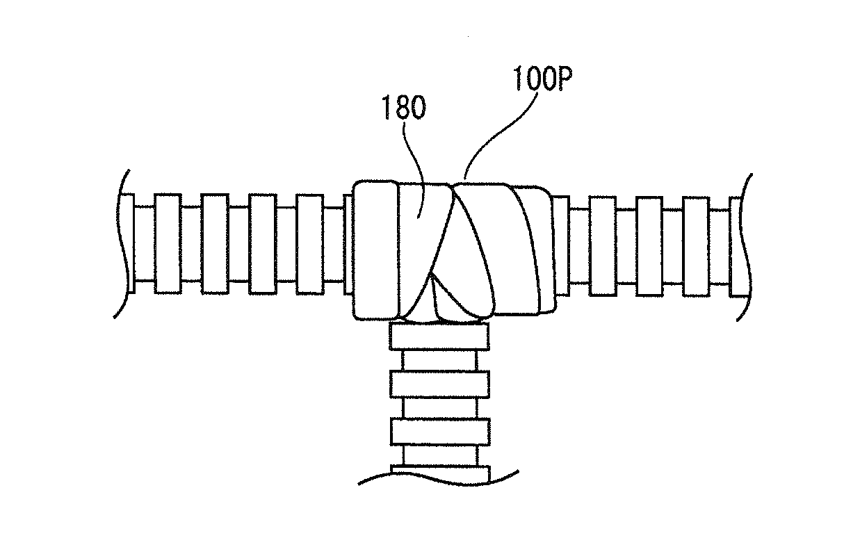
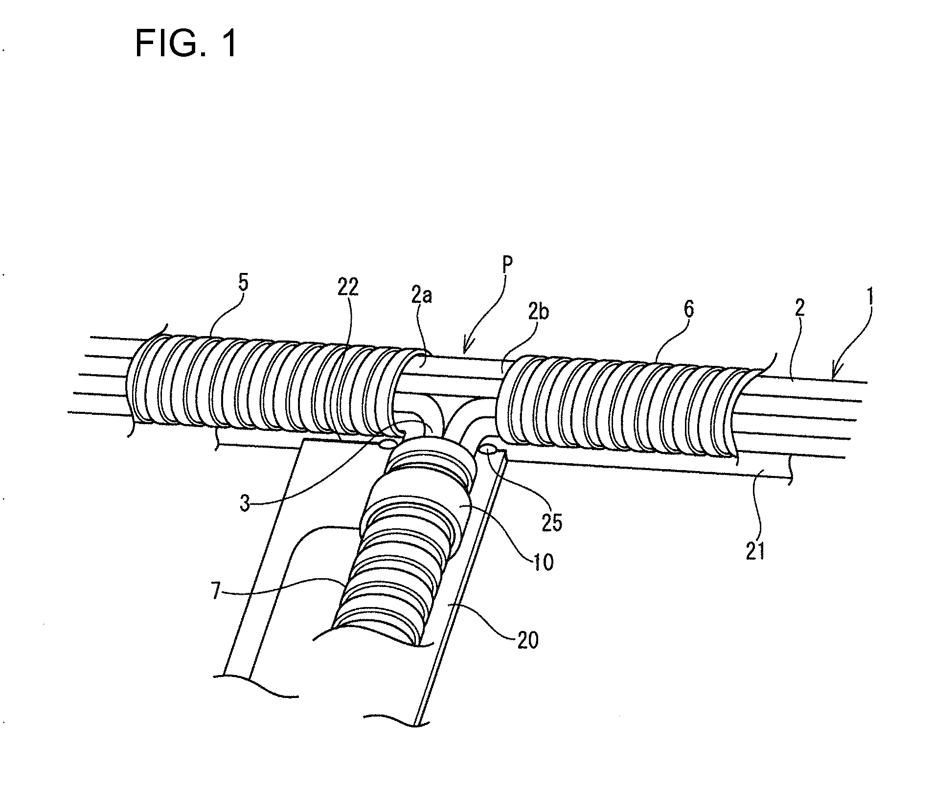
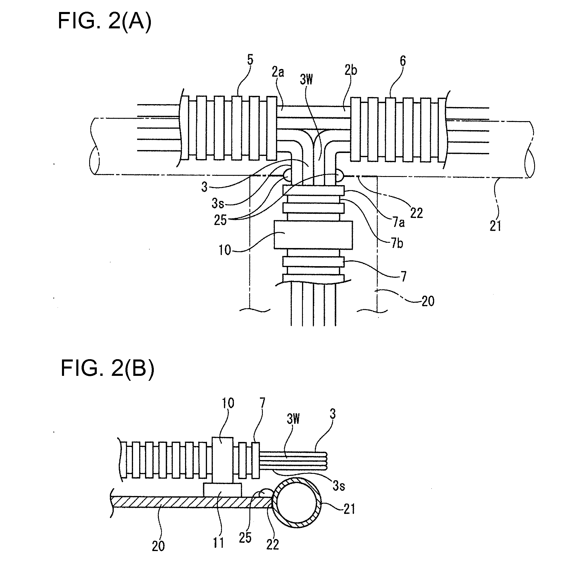
[0024]A wire harness 1 in accordance with the invention is distributed in an instrument panel of a vehicle, as shown in FIG. 1 and FIG. 2. An arc welding portion 22 between an instrument stay 20 and a metal pipe 21 is located downside of and in proximity to a branch position P of a T-shape where branch lines 3 are branched from a trunk line 2 of the wire harness 1. Squeezed-out projections of melted metal spatter at the arc welding portion 22 also are located as external interfering materials 25. The external interfering materials 25 are downside of the branch position P of the wire harness on the side where the branch lines 3 project.

[0025]Corrugated tubes 5 and 6 formed of molded resin are fit on both sides 2a and 2b of the trunk line 2 of the wire harness 1 across the branch position P, and a corrugated tube 7 is fit on the branch lines 3 as well. The corrugated tubes 5, 67 fit on the wire harness 1 cannot be fitted on the branch position P of the T-shape, the trunk line 2 and th...


PUM


Abstract

A wire group of a branch line or a trunk line of a wire harness is covered with a corrugated tube in proximity to an external interfering material projecting from a vehicle body panel. A corrugated clamp is fit fixedly on an end side of the branch portion of the corrugated tube, an outer surface of a vehicle body locking box of the corrugated clamp is brought into abutment with the vehicle body panel having the external interfering material projecting therefrom, and the distance between an outer surface of the wire group covered with the corrugated clamp and the corrugated tube fitted thereon and the external interfering material is larger than the dimension of projection of the external interfering material from the vehicle body panel.

Description

BACKGROUND OF THE INVENTION[0001]1. Field of the Invention[0002]The invention relates to a distribution structure of a wire harness to be distributed in an automotive vehicle and, more specifically, to achieve protection of the wire harness easily and reliably when there is an external interfering material in a route of distribution of the wire harness.[0003]2. Description of the Related Art[0004]A wire harness of an automotive vehicle is connected to electrical components mounted thereon and is distributed in the vehicle. However, an external interfering material, such as a squeezed-out projection of a vehicle body panel formed of metal, or spatter generated from a weld, may exist along the route of the wire harness. External interfering material formed of metal may contact a wire group of the wire harness and break an insulation covering of wire to contact a core wire and create a risk of a short circuit.[0005]JP-A-9-219915 and FIG. 5 herein disclose a harness distribution structu...

Claims


Application Information

Patent Timeline
IPC IPC(8): H02G3/02
CPCB60R16/0215H02G3/32H02G3/0691H02G3/0468
Inventor KITAMURA, KAZUHIRO
Owner SUMITOMO WIRING SYST LTD
Why Eureka
Try Eureka