
Composition for an organic el element and method of manufacturing the organic EL element

a technology of organic el and manufacturing method, which is applied in the direction of bridges, other domestic articles, bridge structural details, etc., can solve the problems of difficult to obtain homogeneous defect-free thin films by vapor deposition method, difficult to select raw materials, and inefficient vapor deposition method, etc., to achieve high precision patterning, simple method, and short time

Inactive Publication Date: 2005-03-17
SEIKO EPSON CORP
View PDF17 Cites 25 Cited by
  • Summary
  • Abstract
  • Description
  • Claims
  • Application Information

AI Technical Summary

Benefits of technology

[0009] It is an object of the present invention to provide a composition for an organic EL element and a method of manufacturing such an EL element which can perform a high precision patterning in a simple manner and in a short time, achieve an optimization of a film design and a luminescence characteristic easily, and facilitate an adjustment of a luminescence efficiency, as well as form a thin film having excellent durability.

Problems solved by technology

Further, since organic compounds are used, there is an unlimited possibility as to the selection of the raw materials.
However, it is difficult to obtain a homogeneous defect-free thin film by the vapor deposition method.
Further, the vapor deposition is not an efficient method, since it takes a long time to form several organic layers by the method.

Method used


Image

  • Composition for an organic el element and method of manufacturing the organic EL element
  • Composition for an organic el element and method of manufacturing the organic EL element
  • Composition for an organic el element and method of manufacturing the organic EL element

Examples


example 1

[0106] The compositions for the organic EL element made from the compositions shown in Table 1 were prepared for respective colors, and then the organic EL element was manufactured using the compositions.

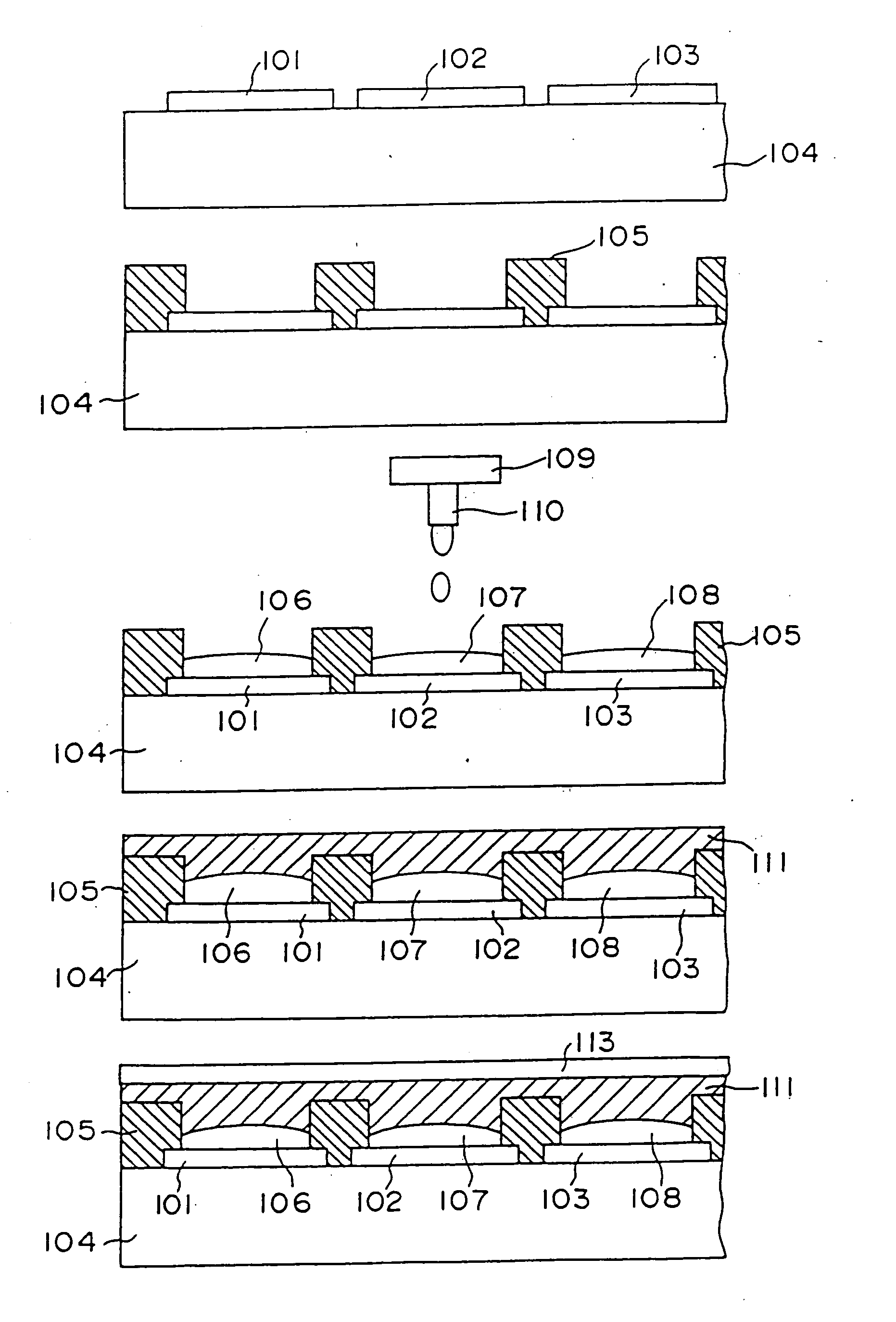
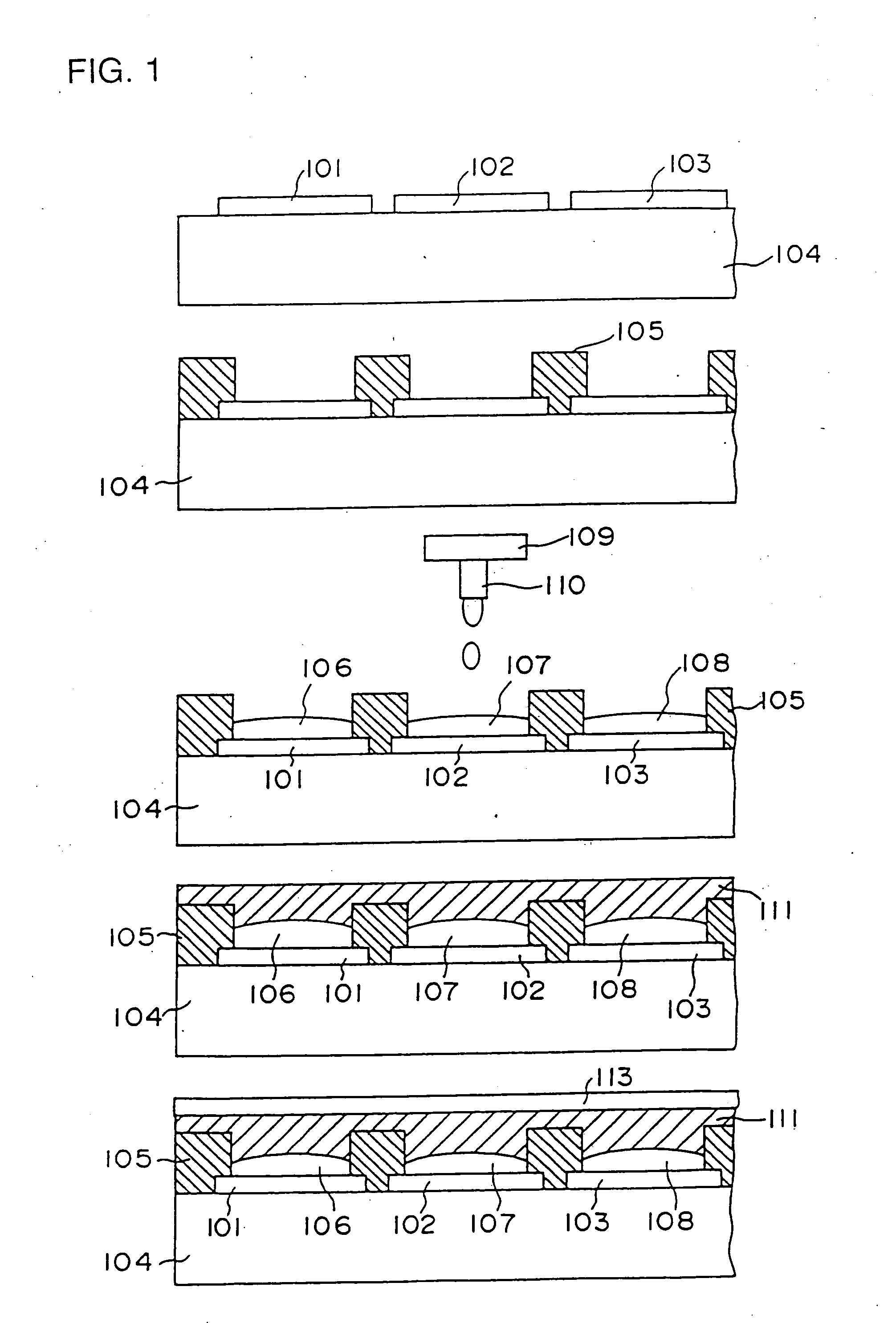
[0107] As shown in FIG. 1, on the glass substrate 104, ITO transparent pixel electrodes 101, 102 and 103 were formed by means of photolithography so as to form respectively a pattern having a pitch of 100 μm and a thickness of 0.1 μm.

[0108] Then, banks 105 made of photosensitive polyimide were formed by photolithography so as to bury the spaces between the ITO transparent pixel electrodes. In this case, each of the banks 105 was designed so as to have a width of 20 μm and a thickness of 2.0 μm, respectively.

[0109] Further, the luminescent materials for the respective colors were coated to form patterns by jetting the compositions from the head 110 of the ink-jet device 109. Then, they were undergone heat treatment under a nitrogen atmosphere at 150° C. for 4 hours to conjugate th...

example 2

[0112] The organic EL element was manufactured in the same way as Example 1 except that quinacridone of 0.075 wt % (ratio for solid portion of PPV precursor: 2 wt %) was added into the green luminescent layer composition as a fluorescent dye as shown in Table 2.

example 3

[0113] The organic EL element was manufactured in the same way as Example 1 except that rhodamine 101 was used as a fluorescent dye in the red luminescent layer composition as shown in Table 3.


PUM

PropertyMeasurementUnit
contact angleaaaaaaaaaa
surface tensionaaaaaaaaaa
voltageaaaaaaaaaa

Abstract

A composition for an organic EL element which can form a high precision pattern in a simple manner and in a short time and a method of manufacturing the organic EL element are disclosed. By using the composition, optimum film design and luminescence characteristic can be easily obtained, and an adjustment of a luminescence efficiency can also be easily performed. The composition for an organic EL element comprises a precursor of a conjugated organic polymer compound for forming at least one luminescent layer (106), (107), (108) having a certain color and at least one kind of fluorescent dye for changing the luminescence characteristic of the luminescent layer. The luminescent layer is made from a pattern formed by an ink-jet method. As for the precursor, a precursor of PPV, PPV derivative or the like is preferably used. Further, it is preferable that the composition for the organic EL element satisfies at least one of the conditions including a contact angle of 30 to 170 degrees with respect to a nozzle surface of a nozzle provided in a head of an ink-jet device used for the ink-jet method for discharging the composition, a viscosity of 1 to 20 cp and a surface tension of 20 to 70 dyne / cm.

Description

BACKGROUND OF THE INVENTION [0001] 1. Field of the Invention [0002] The present invention relates to a composition for an electroluminescent (EL) element, and more particularly, to a composition for an organic EL element, and a method of manufacturing the organic EL element. [0003] 2. Description of the Background Art [0004] An organic EL element has a constitution in which a cathode and an anode are connected to the opposite sides of a solid thin film containing a fluorescent organic compound. When a voltage is applied across the electrodes, electrons and holes are injected into the thin film, and they migrate according to the generated electric field and recombine with each other. At the time, excitons are produced by the energy liberated upon the recombination, and energy (in the form of fluorescence or phosphorescence) is emitted when the excitons are returned to the ground state thereof. This phenomenon is called electroluminescence. [0005] The characteristic of an organic EL e...

Claims


Application Information

Patent Timeline
Patent Type & Authority Applications(United States)
IPC IPC(8): C09K11/06H01L27/32H01L51/00H01L51/30H01L51/40H01L51/50H05B33/10H05B33/14
CPCC09K11/06C09K2211/1408C09K2211/1425H01L27/3295Y10S428/917H01L51/0038H01L51/5012H05B33/10H05B33/14H01L51/0005H10K59/173H10K71/135H10K85/114H10K50/11E01D19/106E01D22/00
Inventor KIGUCHI, HIROSHIKANBE, SADAOSEKI, SHUNICHI
Owner SEIKO EPSON CORP
Learn More