Method and Apparatus for Combining AC Power Relay and Current Sensors with AC Wiring Devices

a technology of ac power relay and current sensor, which is applied in the direction of relays, manufacturing tools, sustainable buildings, etc., can solve the problems of not being able to positively verify the on-off power status of a remote site, back the needed power consumption reporting, and complex verification of the operation status of a remotely operated appliance, etc., to achieve the convenience and efficiency of remote switching

Active Publication Date: 2012-10-18
ELBEX VIDEO LTD
View PDF1 Cites 97 Cited by
  • Summary
  • Abstract
  • Description
  • Claims
  • Application Information

AI Technical Summary

Benefits of technology

[0041]The method of combining packaged AC relay devices including current sensor to an existing standard electrical switches, introduces several major advantages; one is the lowering of the overall cost of the switches, because standard low cost, mass produced switches can be used. The second advantage is that the manual actuating of the commonly used switches is all that it takes to operate the switch (the way the switches are operated presently) with the present invention provides the ability to operate the switches remotely, in parallel by wireless remote control units, keypads, dedicated controller, video interphone monitor and via the Internet or mobile phones or iPad.
[0044]Accordingly, another of the objects of the present invention is to attach a lightguide to an IR controlled SPDT relay connected to one of an SPDT and DPDT light switch for operating a light fixture or other electrical appliance via one or several manual switches in cascade. Thereby maintaining the operation via a “commonly used” manual switch and provide the conveniences and efficiency of remote switching via the wireless or lightguide controlled SPDT relay connected to the one or several switches in a given configuration.

Problems solved by technology

Verifying the operation status of a remotely operated appliance however is complex.
Most of the remote control devices including IR or RF wireless remote control units use the same power key (and code) to switch the appliance on and off, therefore without the operating person's self verification on site, with most of currently available remotely controlled systems it is impossible to positively verify the on-off power status from a remote site.
The problems such system represents are a. the need to re-design the whole electrical wiring system requiring the customizing of the AC electrical wiring structure and expertise to configure, install and maintain, all of which are expensive and b. the current drain reporting on the basis of the relay status does not reliably provide real time statuses, for example, a boiler's relay status will remain on even though no current is drained when the boiler's power is cut by the boiler thermostat.
The problem however for such remote controlling is the need for a verified on-off status of the appliances being operated and / or the availability of a status report covering all the remotely controlled appliances of a given house, office, apartment or a building.
But the electrical safety codes and regulations that forbid connections of a low voltage communication line to an AC power switch and AC power outlets held back the needed power consumption reporting until now.
However, the users do not prefer to have two adjacent devices for operating for example, the same light, and moreover it is not architecturally pleasing to expand the number of electrical boxes, switching devices and / or lineup decorative covers on the walls, and a need for a less visible or non-noticeable integration of the remotely operated SPDT relays with the standard manually actuated SPDT switches is needed.

Method used


Image

  • Method and Apparatus for Combining AC Power Relay and Current Sensors with AC Wiring Devices
  • Method and Apparatus for Combining AC Power Relay and Current Sensors with AC Wiring Devices
  • Method and Apparatus for Combining AC Power Relay and Current Sensors with AC Wiring Devices

Examples


Embodiment Construction

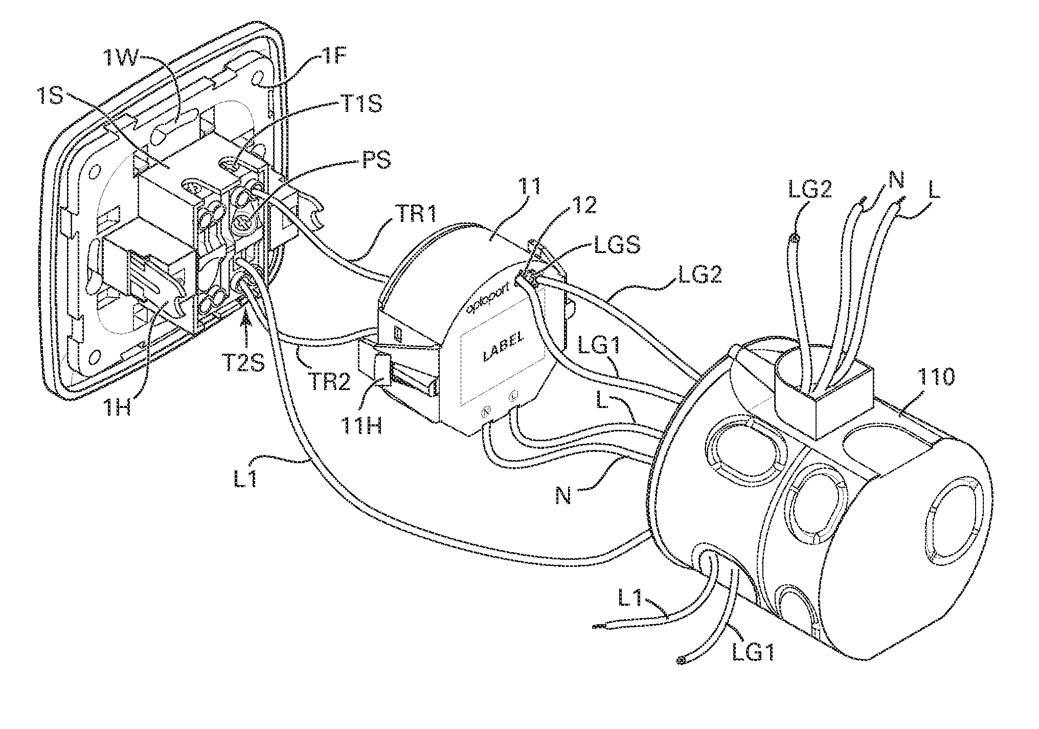
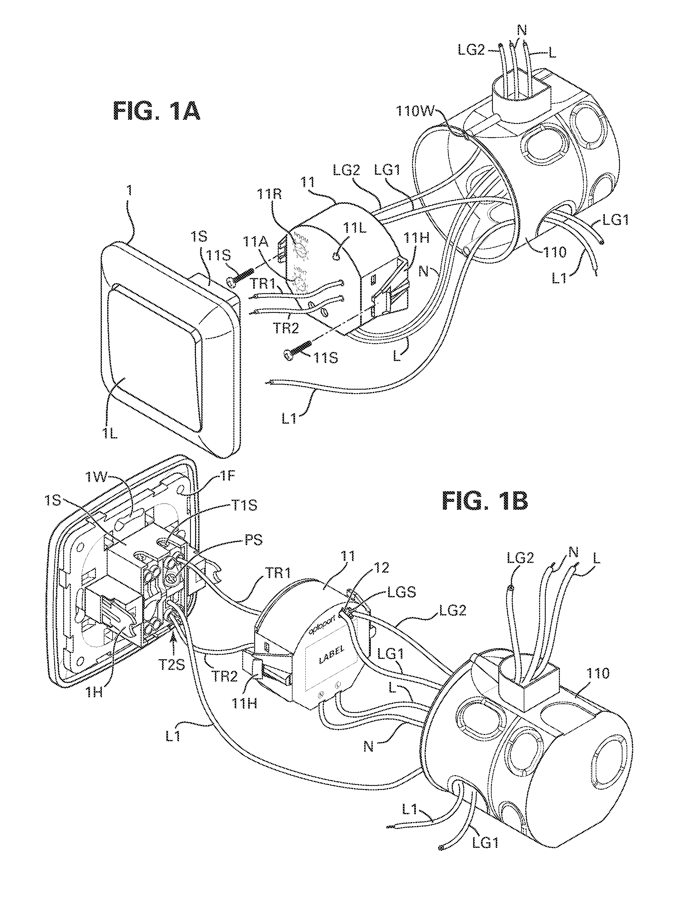
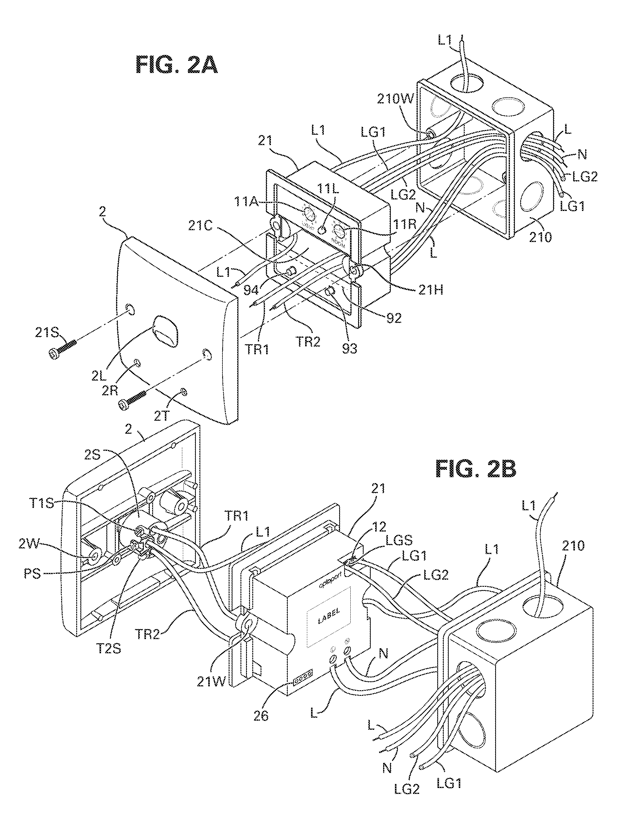
[0064]FIG. 9A shows a block diagram summarizing the on-off switching circuit for operating AC appliances such as heaters or light fixtures, manually through an SPDT switch 8 and remotely by the SPDT relay 96 of the AC switching devices 11, 21, 31, 41, 51, 61 or 71 shown in FIGS. 1A˜7B. The known single pole-dual throw (SPDT) switch 8 includes a lever actuated spring contact P that enables to switch over the power from traveler terminal T1 to T2 for connecting AC power to an appliance or a load in combination with the remotely operated mechanical or semiconductor SPDT relay of the AC devices 11˜71 used for home automation and disclosed in the referenced US patent and applications. The SPDT relay contacts, similar to the SPDT switch, connect or break the AC current fed to an AC appliance via the relay assembly 96 of AC switching device 11, representing hereafter each of the AC switching devices 11, 21, 31, 41, 51, 61 and 71 shown in FIGS. 1A˜7B.

[0065]The combining of the SPDT switch w...


PUM

PropertyMeasurementUnit
diameteraaaaaaaaaa
DC voltageaaaaaaaaaa
sizeaaaaaaaaaa

Abstract

A method and a device for joining a remotely controlled switching and current sensing AC device structured for attachment to standard and popular three way SPDT AC switches or cross DPDT AC switches and / or power outlets, such that the front wall plate of a single gang electrical box will cover the joined AC device with the manual switch or the AC outlet. The AC device is operated and communicates via lightguide or fiber optic cable using two way optical signals and via IR in air in line of sight and / or via RF in air. The lightguide is cascaded in series from one AC device to another and / or from a joint switch device to a joined AC outlet and to an optoport in front of an outlet socket for communicating the current drain and / or operation controls with the appliance, powered by the AC socket, via a lightguide included in the power cable with plug assembly of the appliance.

Description

BACKGROUND OF THE INVENTION[0001]1. Field of the Invention[0002]This invention is related to remotely operating SPDT AC power semiconductor switches or relays used in home automation operated via wireless remote control or plastic optical fiber and lightguide cables in combination with mechanical SPDT power switches, including current sensors and power outlets.[0003]2. Description of the Prior Art[0004]Remotely operating AC power relays switch on and off electrical appliances such as home heaters, air conditioners, motorized curtains, lighting and other electrical appliances in homes, apartments, offices and buildings. Verifying the operation status of a remotely operated appliance however is complex. Almost all of the appliances do not report their status and the person operating the remote control device has to verify the on or off status of the operated device by being at the site of the operated appliance and see for himself if the lights are on or off, or the aircondition unit ...

Claims


Application Information

Patent Timeline
Patent Type & Authority Applications(United States)
IPC IPC(8): H01H47/00H05K13/04H01R43/00
CPCH01H9/167H02G3/12Y02B90/224Y10T29/49117Y04S20/14H01H2300/03Y02B90/20H01H47/22
Inventor ELBERBAUM, DAVID
Owner ELBEX VIDEO LTD
Why Eureka
Try Eureka