Low profile, high flowthrough smoke chamber

a smoke chamber and low-profile technology, applied in measurement devices, instruments, scientific instruments, etc., can solve problems such as adversely affecting the sensitivity of the detector, generating undesirable frictional forces, and interference in the cross-path of airflow, and achieve the effect of quick and efficient entry and exi

Inactive Publication Date: 2012-10-18
UNIVERSAL SECURITY INSTR
View PDF6 Cites 22 Cited by
  • Summary
  • Abstract
  • Description
  • Claims
  • Application Information

AI Technical Summary

Benefits of technology

[0007]It is an object of the invention to provide a smoke chamber design that provides a minimally obstructed air flow path for ambient air and smoke particles to quickly and efficiently enter and exit the smoke chamber.

Problems solved by technology

The presence of multidirectional obstructions in an airflow path not only can create airflow cross-path interference and counter-flow conditions, but also can generate undesirable frictional forces between the baffles / vanes and the airborne particulates.
Introduction of frictional forces can adversely impact the sensitivity of the detector by reducing the air flow volume and impeding the movement of airborne particles.
Such interference can cause a loss of energy resulting in a number of the particles to adhere to the obstructing baffles / vanes and a concomitant loss of sensitivity.
In short, traditional labyrinth-type smoke chambers by necessity, sacrifice a minimally obstructed or otherwise direct airflow path thereby causing a reduction in detection efficiency by retarding detection speed attributable to increased time for a necessary population of smoke particles to accumulate before a sufficient concentration accumulates to trigger an alarm event responsive to a fire condition.
The foregoing structures do not provide a substantially uninterrupted flow path for ambient air to move in and out of the sensing chamber of a photoelectric detector.

Method used


Image

  • Low profile, high flowthrough smoke chamber
  • Low profile, high flowthrough smoke chamber
  • Low profile, high flowthrough smoke chamber

Examples


Embodiment Construction

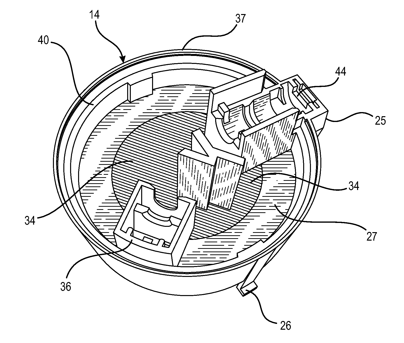
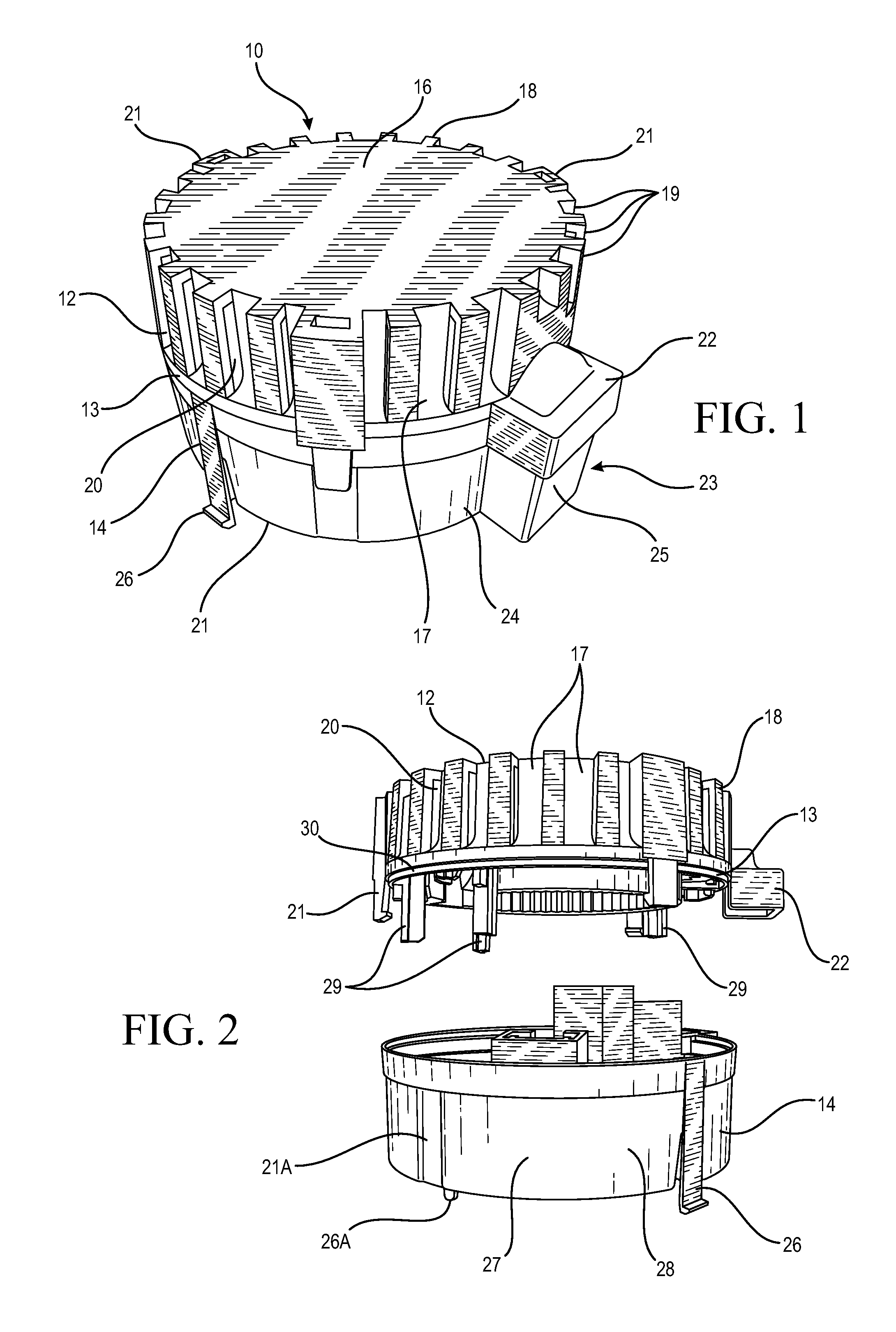
[0024]FIG. 1 illustrates a low profile smoke sensing chamber assembly 10 according to an embodiment of the invention. The assembly 10 comprises a vented top cover 12 affixed to a chamber base 14. As illustrated, the assembly 10 is cylindrical and is of a height significantly less than the assembly diameter. The top cover 12 is defined by an upper portion which is established by a planar disk-like member 16 with a plurality of perimetric, vertically disposed columns 18 with interposed vertical gaps 19 therebetween. The columns 18 and gaps 19 are concentric and depend axially almost the entire height of the top cover 12 excepting the lower edge 13. The gaps 19 extend a short distance radially inward to vertically disposed, depending pillars 17 which alternate with the columns 18. Radially oriented air flow vent passages 20 are established between the back edge of a respective column and the front edge of an adjacent pillar. Consequently, the vertical air vent passages 20 are establish...


PUM

PropertyMeasurementUnit
heightaaaaaaaaaa
heightsaaaaaaaaaa
electrical poweraaaaaaaaaa

Abstract

A low profile optical smoke chamber structure with a top cover incorporating airflow slots, an intermediate annular air channel, a depending light shield wall surrounding an interior detection chamber where the top cover is interengagable with a base member where the light shield wall is spaced from the base member so as to provide minimal deflection of ambient airflow into the detection chamber while preventing impingement of ambient light therein.

Description

FIELD OF THE INVENTION[0001]The disclosed invention relates to the art of optical hazardous condition detector devices in general and a new and useful smoke chamber design optimized for directed, minimally perturbed air flow to provide improved sensitivity particularly in the case of photoelectric smoke detectors.BACKGROUND[0002]Photoelectric smoke detectors usually work on the same principle but follow one of two common configurations. In one case, activation of the photoelectric detector occurs when a light focused on a light-sensitive sensor is obstructed or blocked by particulate matter in the ambient air of the type contained in smoke. The second type of detector relies on detection of scattering from a light source. In the detector's smoke chamber, light from an appropriate source impinges on and is scattered / reflected by the airborne particulates of the type resulting from a smoldering fire which is detected by a light receiving device, such as a photodiode.[0003]To balance t...

Claims


Application Information

Patent Timeline
Patent Type & Authority Applications(United States)
IPC IPC(8): G01N21/53
CPCG01N21/4738G01N21/53
Inventor GONZALES, ERIC V.
Owner UNIVERSAL SECURITY INSTR
Why Eureka
Try Eureka