Device and method of using the same for removing a flowable material contained within a vessel or cavity

a flowable material and device technology, applied in the direction of machines/engines, respirators, water supply installations, etc., can solve the problems of limiting the extent and the area that can be effectively treated and the amount of material, affecting the removal effect of flowable material, etc., to achieve the effect of enhancing the removal of flowable material, minimizing damage or disruption of the vessel or cavity, and minimizing damage or disruption to immediate areas

Inactive Publication Date: 2012-11-01
WALDMAN ALAN A
View PDF3 Cites 2 Cited by
  • Summary
  • Abstract
  • Description
  • Claims
  • Application Information

AI Technical Summary

Benefits of technology

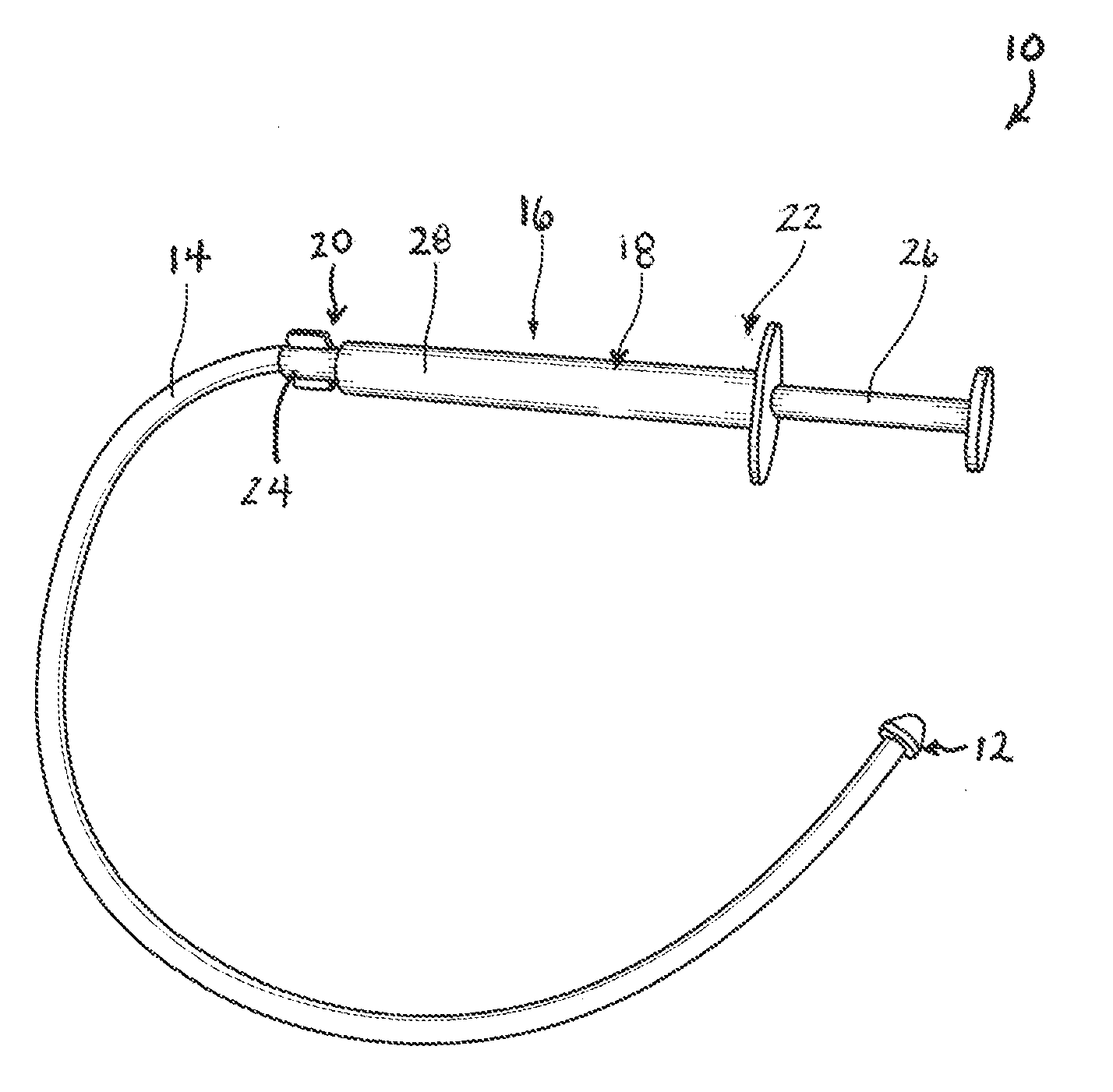
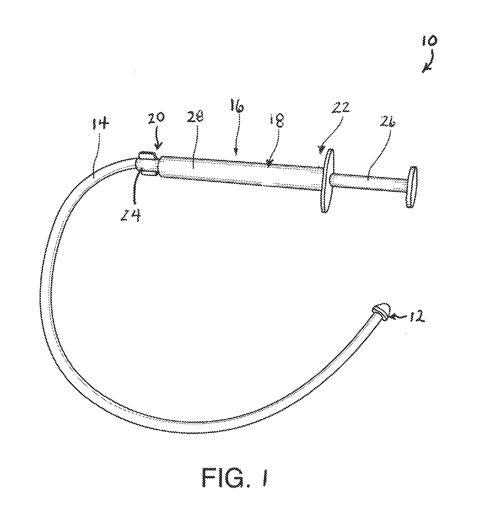
[0008]The present invention relates generally to devices and methods of using such devices for removing a flowable material such as a fluid contained within a vessel or cavity. Broadly, the device of the present invention includes a nozzle body configured for removing the flowable material from the vessel or cavity, and negative pressure generating means operatively associated with the nozzle body for generating negative pressure sufficient to draw the flowable material into the nozzle body in a manner that substantially minimizes damage or disruption of the vessel or cavity. The device of the present invention is designed to direct negative pressures associated with aspiration, removing or suctioning away from the distal end thereof, thereby significantly minimizing damage or disruption to immediate areas of the vessel or cavity (e.g., mucosal lining of tissue). As a result, the device of the present invention may be placed substantially closer to the surface of the vessel or cavity to enhance removal of the flowable material from the site. The present device enables greater levels of negative pressure to be achieved, while maintaining safety and reliability.
[0009]In the present invention, devices, including medical and non-medical devices and kits comprising a plurality of such devices form part of the invention. During operation, the device of the present invention is used to draw or remove a flowable material such as a fluid at a site within the interior cavity or vessel, while avoiding or at least substantially minimizing any injury or disruption to the surrounding inside surfaces of the interior cavity or vessel due to high back pressure.
[0015]negative pressure generating means operatively associated with the outlet for generating negative pressure at the second side portion thereof sufficient to draw the flowable material therein without damaging or substantially disrupting the vessel or cavity.
[0025]generating negative pressure at the second side portion of the nozzle body sufficient to draw the fluid from the vessel or cavity into the nozzle body without damaging or substantially disrupting the vessel or cavity.
[0026]The present invention as herein described by making the second side portion permeable to the flowable material (and not the first portion) minimizes occlusion of the device that can occur when, as in prior art devices, the permeable portion is positioned proximate the vessel walls.

Problems solved by technology

The tissues around the fluids are sensitive to pressure and could be injured if excessive suction is applied.
In addition to mucosal trauma, tracheal or endotracheal suctioning is often associated with other potentially harmful complications including hypoxemia, diminished cerebral blood flow, and vasovagal response causing arrhythmias and hypotension.
These restrictions limit the extent and the areas that can be effectively treated and the amount of material that can be removed from a given treatment area.
This limits the effective area of the open portion of the suctioning device.

Method used


Image

  • Device and method of using the same for removing a flowable material contained within a vessel or cavity
  • Device and method of using the same for removing a flowable material contained within a vessel or cavity
  • Device and method of using the same for removing a flowable material contained within a vessel or cavity

Examples


second embodiment

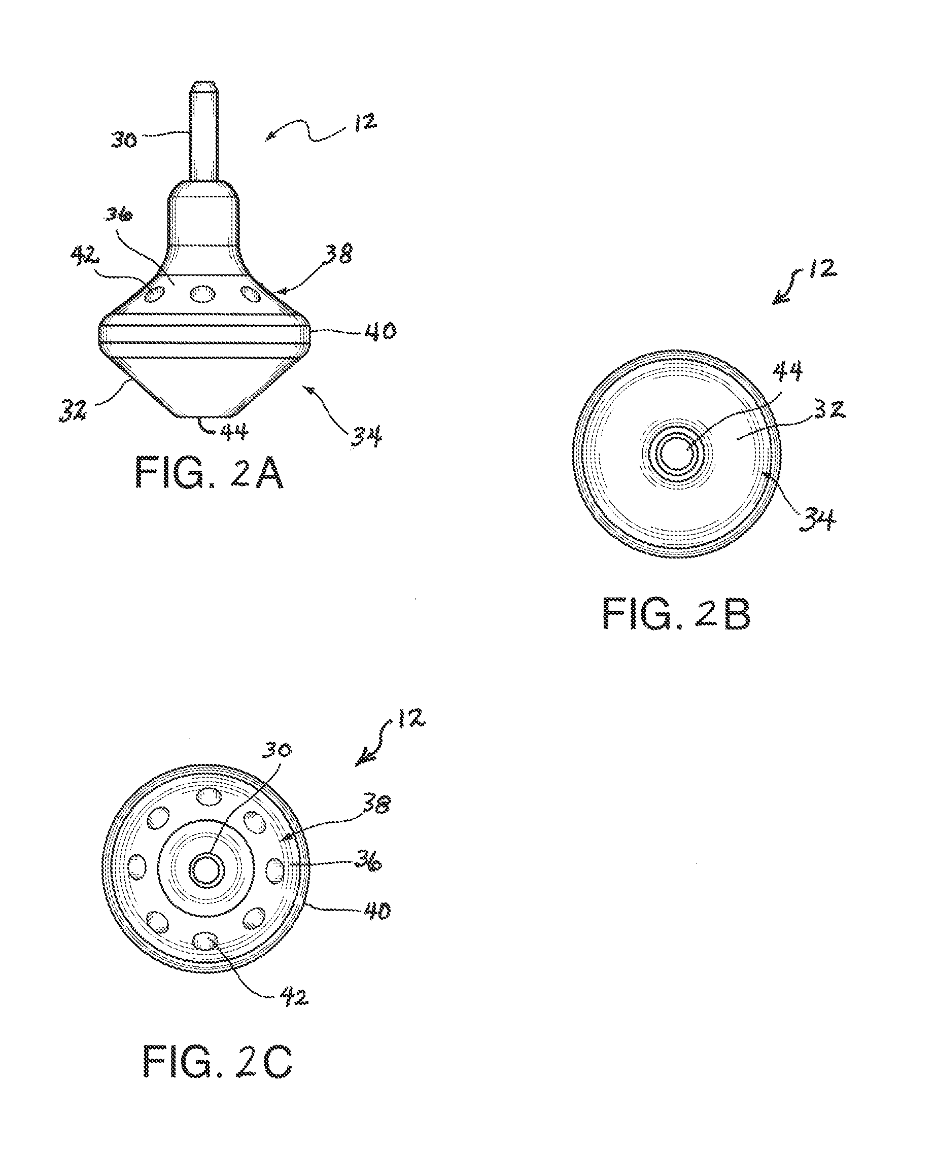
[0120]In reference to FIGS. 4A-4C, there is shown a nozzle body identified generally by reference numeral 70 for the present invention. The nozzle body 70 is structurally and functionally similar to the embodiment of FIGS. 2A-2E. In the present embodiment, the nozzle body 70 includes a flattened or truncated first side portion 72 disposed opposite from an outlet 74, and a second side portion 76 with a straight profile to form a low conical shape. Four apertures or inlets 78 are disposed radially spaced-apart from one another in the second side portion 76. The truncated first side portion 72 allows the nozzle body 70 to be placed close to the inner surface of the cavity 60 thereby facilitating removal of a greater amount of the flowable material 66.

third embodiment

[0121]In reference to FIGS. 5A-5C, there is shown a nozzle body identified generally by reference numeral 80 for the present invention. The nozzle body 80 is structurally and functionally similar to the embodiment of FIGS. 4A-4C. In the present embodiment, the nozzle body 80 includes a flattened or truncated first side portion 82 disposed opposite from an outlet 84, and a second side portion 86 with a straight profile to form a high conical shape. Four apertures or inlets 88 are disposed radially spaced-apart from one another in the second side portion 86. The truncated first side portion 82 allows the nozzle body 80 to be placed close to the inner surface of the cavity 60 thereby facilitating removal of a greater amount of the flowable material 66. The high conical shape of the second side portion 86 allows the size of the inlets 88 to be increased, which better accommodates the passing of thicker or more viscous flowable material 66 therethrough.

fourth embodiment

[0122]In reference to FIGS. 6A-6C, there is shown a nozzle body identified generally by reference numeral 90 for the present invention. The nozzle body 90 is structurally and functionally similar to the embodiment of FIGS. 4A-4C. In the present embodiment, the nozzle body 90 includes a second side portion 92 with a convex profile to form a low hemispherical shape. Four apertures or inlets 94 are disposed radially spaced-apart from one another in the second side portion 92.


PUM


Abstract

A device for removing a flowable material such as a fluid contained within a vessel or cavity includes a nozzle body having an outlet, a first side portion impermeable to the flowable material located distally from the outlet, a second side portion permeable to the flowable material located proximate to the outlet, the second side portion being in fluid communication with the outlet through the nozzle body, and negative pressure generating means operatively associated with the outlet for generating negative pressure at the second side portion of the nozzle body sufficient to draw the flowable material into the nozzle body without damaging or substantially disrupting the vessel or cavity. Methods of using the same are also disclosed.

Description

RELATED APPLICATIONS[0001]This Application claims the benefit of priority from U.S. Provisional Patent Application Ser. No. 61 / 571,407, filed on Jun. 27, 2011, and U.S. Provisional Patent Application Ser. No. 61 / 517,788, filed on Apr. 26, 2011, the contents of which is incorporated herein by reference in the entirety.FIELD OF THE INVENTION[0002]The present invention relates to devices, including medical and non-medical devices, and particularly to devices and methods of using the same for removing a flowable material such as a fluid from a site within the interior of a vessel or cavity in a safe and reliable manner.BACKGROUND OF THE INVENTION[0003]It is known in the art to draw or remove fluid from a site within an enclosed cavity or vessel. Among other applications, in the medical field, there is a need for removing fluids pursuant to a treatment regimen. For example, in a medical procedure, a surgical site is typically irrigated with a physiological aseptic solution and then sucti...

Claims


Application Information

Patent Timeline
Patent Type & Authority Applications(United States)
IPC IPC(8): E03B5/00
CPCA61M15/08A61M2210/0618A61M1/007A61M1/008A61M16/0484A61M2210/1032Y10T137/86083Y10T137/0318A61M1/815A61M1/84
Inventor WALDMAN, ALAN A.
Owner WALDMAN ALAN A
Why Eureka
Try Eureka