Riding type vehicle and method of controlling riding type vehicle

a technology of riding type and riding mode, which is applied in the direction of electric/hybrid propulsion, non-deflectable wheel steering, wheelchairs/patient conveyances, etc., can solve the problems of difficulty in operation, inability to accurately calculate the corrected amount, and more likely to cause accidents

Active Publication Date: 2012-11-08
PANASONIC CORP
View PDF12 Cites 44 Cited by
  • Summary
  • Abstract
  • Description
  • Claims
  • Application Information

AI Technical Summary

Benefits of technology

[0023]As described above, according to the riding type vehicle and the method of controlling the riding type vehicle, by the provision of the posture sensor disposed on the backrest, the operational intention determining unit that makes the determination using a contact area and the intensity of contact pressure as indices, and the left-right amount-of-change comparison type turn intention determining unit, a safe riding type vehicle and a safe method of controlling a riding type vehicle can be provided in which even if a large postural change occurs as a result of the intention of performing motion other than operation, the vehicle does not erroneously make a left or right turn or perform a movement operation.

Problems solved by technology

However, although Patent Literature 1 proposes an equipment control means that allows a user to perform operation with human's natural sense of direction indication and without using his / her hand, even when an unintentional postural change occurs, if the postural change is detected as a physical variable quantity, then the mobility equipment is controlled and thus operation of the mobility equipment that is against the rider's intention is performed.
Therefore, Patent Literature 1 not only provides difficulty in operation but is also likely to cause accidents.
However, even without a rider's operational intention, when a large postural change occurs as a result of the intention of performing motion other than operation, a corrected amount change cannot be accurately calculated and thus the equipment is controlled against the intention.
For example, when a person extends his / her hand to try to pick up an object on his / her left or right at getting in or out of the equipment or during riding, in many cases, the rider's posture is changed to an unstable riding posture, which rather causes an issue that accidents are more likely to be caused.

Method used


Image

  • Riding type vehicle and method of controlling riding type vehicle
  • Riding type vehicle and method of controlling riding type vehicle
  • Riding type vehicle and method of controlling riding type vehicle

Examples


first embodiment

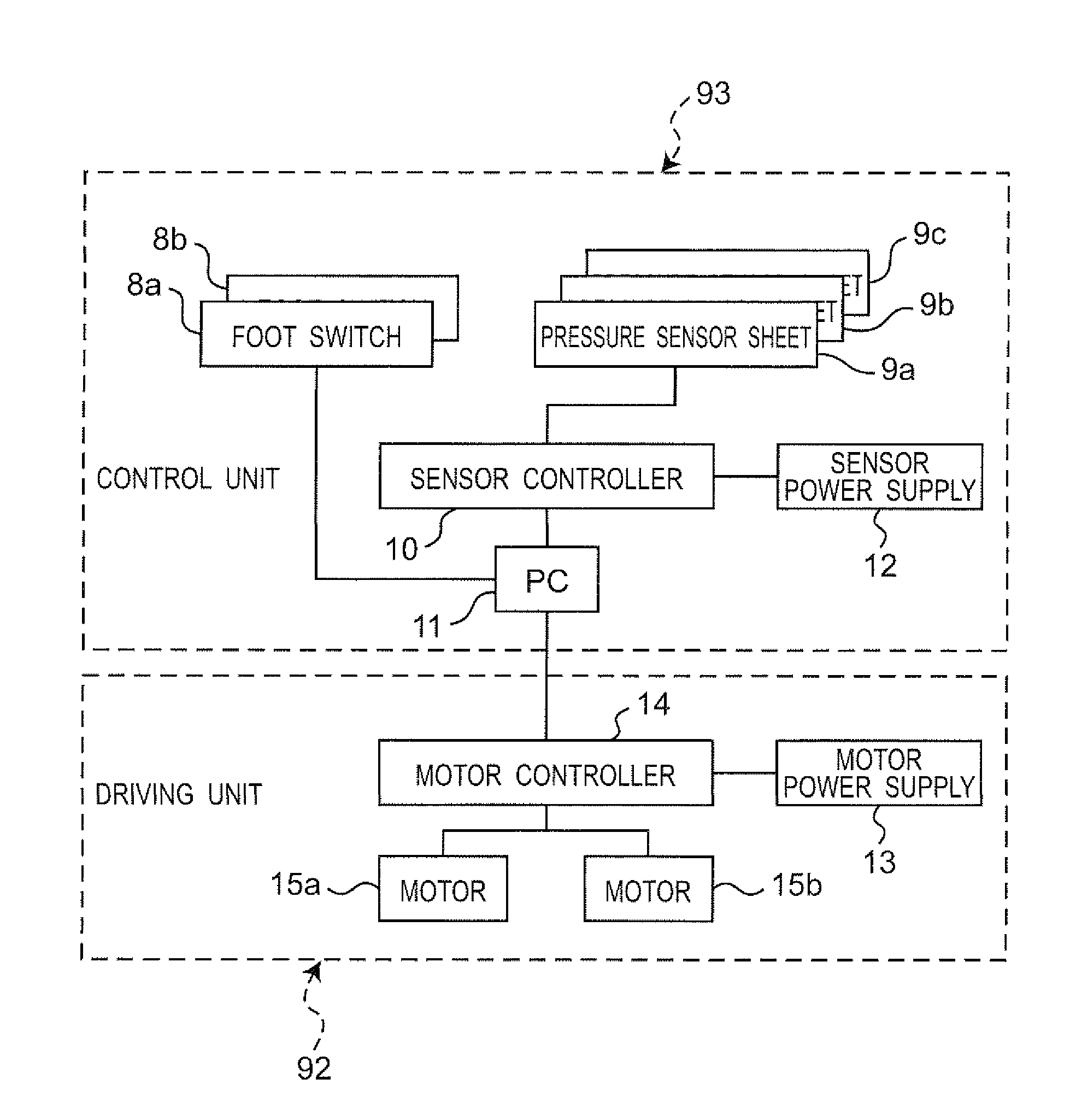
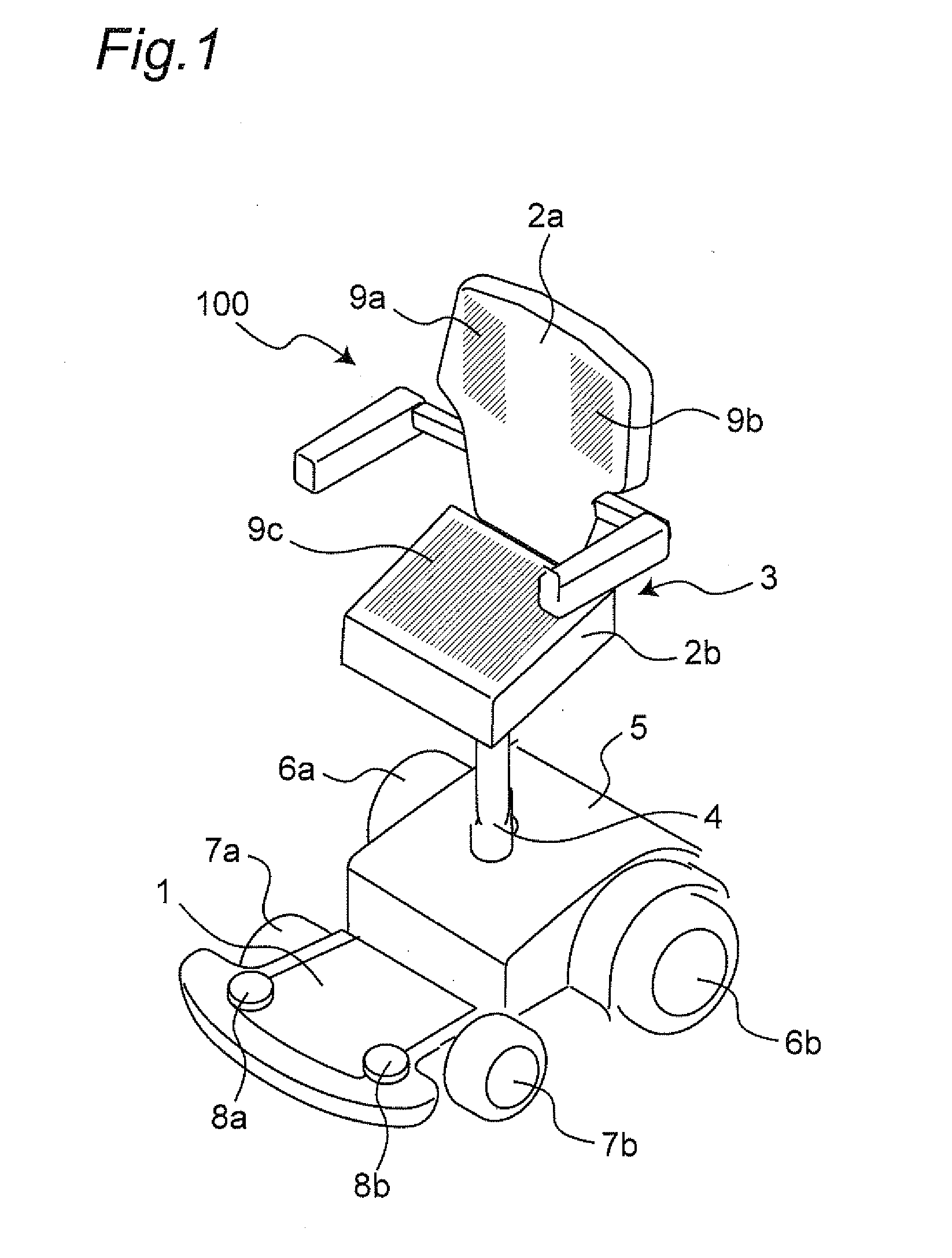
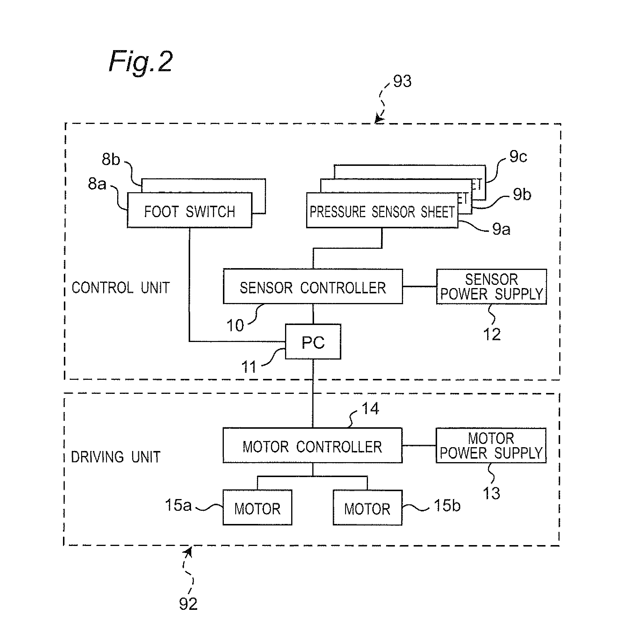
[0289]FIGS. 1 and 2 are an external view and a block diagram of a hardware configuration of a standing position riding type vehicle 100 which is an example of a riding type vehicle (an example of mobility aid equipment) which a method of controlling a riding type vehicle according to a first embodiment of the present invention can be applied.

[0290]Note that in the following description a portion of the vehicle 100 with which the upper body of a rider 91 which is a part above his / her lower back comes into contact when the rider 91 rides in the vehicle 100 is referred to as a backrest, and a portion of the vehicle 100 with which the lower body of the rider 91 which is a part below his / her hip joint comes into contact is referred to as a seat portion. Note also that regions including left and right shoulder blades 50a and 50b of the rider 91 and further including back portions 51a and 51b where the back ribs are located at the width of the shoulder blades are referred to as backrest up...

second embodiment

[0326]In a riding type vehicle and a method of controlling a riding type vehicle according to a second embodiment of the present invention, a pressure sensor sheet for a backrest lower central portion (an example of a pressure sensor) 9d which functions as an example of a posture sensor for a backrest lower central portion is additionally disposed in a lower central portion of a backrest 2a, whereby a postural change with a turn operation intention and postural changes caused by other activities can be more accurately identified over the first embodiment.

[0327]Specifically, in the first embodiment, stable operation can be performed by postural change in both of the case in which a rider 91 sits back in a seat portion 2b and the case in which the rider 91 sits on the edge of the seat portion 2b while leaning against the backrest 2a; however, the former case in which the rider 91 sits back gives the rider 91a greater sense of security in actual operation while moving. When it is premi...

third embodiment

[0353]In the following riding type vehicle and method of controlling a riding type vehicle according to a third embodiment of the present invention, an embodiment is described which means for notifying a rider 91 (notifying unit), e.g., a speaker 20, is additionally disposed in the first embodiment.

[0354]FIGS. 15 and 16 are an external view and a block diagram of a hardware configuration of a vehicle 100 of the third embodiment of the present invention. The positions of pressure sensor sheets 9a, 9b, and 9c are the same as those in FIGS. 3A and 3B in the first embodiment.

[0355]On / off output signals from foot switches for forward and backward motion 8a and 8b are executed in the specifications described in the first embodiment, enabling forward and backward motion by the foot switches 8a and 8b

[0356]Left and right turns are made using the posture sensors 9a, 9b, and 9c in the same manner as in the above-described first and second embodiments. Here too, as the posture sensors 9a, 9b,...


PUM


Abstract

A vehicle includes a contact-position-dependent type operational intention determining unit that detects a change in posture of a rider using posture sensors for a backrest disposed in areas of a backrest with which left and right shoulder blades of the rider come into contact, and thereby determines whether there is an operational intention of the rider; and a left-right amount-of-change comparison type turn intention determining unit that determines, only when it is determined that there is an operational intention, whether there is a left or right turn intention of the rider from a difference between sensor output values located left-right symmetrically.

Description

CROSS-REFERENCE TO RELATED APPLICATIONS[0001]This is a continuation application of International Application No. PCT / JP2011 / 005101, with an international filing date of Sep. 9, 2011, which claims priority of Japanese Patent Applications Nos. 2010-204122, 2010-223501, and 2011-028077 filed on Sep. 13, 2010, Oct. 1, 2010, and Feb. 14, 2011, the contents of which are incorporated herein by reference.TECHNICAL FIELD[0002]The present invention relates to a riding type vehicle and a method of controlling a riding type vehicle, in which a rider performs operation control by postural change.BACKGROUND ART[0003]Compact single-seat mobility aid equipment represented by a motorized wheelchair, etc., normally uses a joystick as operating means. A user uses a joystick to indicate direction by holding an end of the lever that can freely pivot in all directions with his / her hand and tilting the lever in an intended turn direction. Although the joystick provides easiness to allow to indicate all di...

Claims


Application Information

Patent Timeline
Patent Type & Authority Applications(United States)
IPC IPC(8): G06F7/00A61G5/04B60N2/75B60N2/90
CPCA61G5/04Y10T477/10B60L15/2036B60L2200/24B60L2200/44B60L2240/423B60N2/449B60N2/46B60N2/643B60N2/646B62D1/02B60N2002/247Y02T10/642B60N2/002B60N2/245A61G2203/44B60L2200/26Y02T10/7275A61G2203/10B60N2/986B60N2/75Y02T10/64Y02T10/72Y02P90/60
Inventor WAKITA, YUMIKATO, YUMIKOSAKAKIBARA, MIZUHOINOUE, KENICHI
Owner PANASONIC CORP
Why Eureka
Try Eureka