
KVM switch with embedded bluetooth module

Active Publication Date: 2012-11-08
ATEN INT CO
View PDF6 Cites 27 Cited by
  • Summary
  • Abstract
  • Description
  • Claims
  • Application Information

AI Technical Summary

Benefits of technology

[0010]The present invention is directed to a computer switch, such as a KVM switch, which allows a user to use the same non-Bluetooth enabled user console device to control Bluetooth master machines via the KVM switch in the same manner as controlling conventional computers directly connected to the KVM switch.
[0011]An object of the present invention is to provide a more versatile computer switch system for selectively controlling multiple computers.

Problems solved by technology

While tablet computers and smart handheld devices have become more popular and are equipped with more advanced functions so that they can almost achieve the functions of notebook or desktop computers, because these products use touch screen as user input interface, it is not very convenient for the user to input text.

Method used


Image

  • KVM switch with embedded bluetooth module
  • KVM switch with embedded bluetooth module
  • KVM switch with embedded bluetooth module

Examples


first embodiment

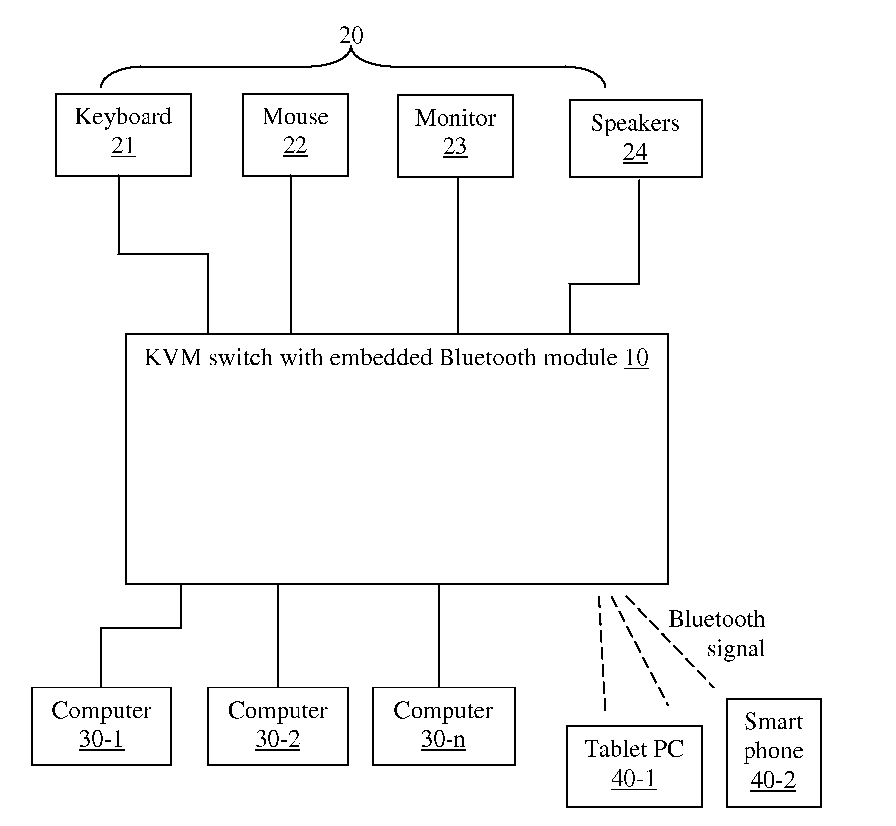
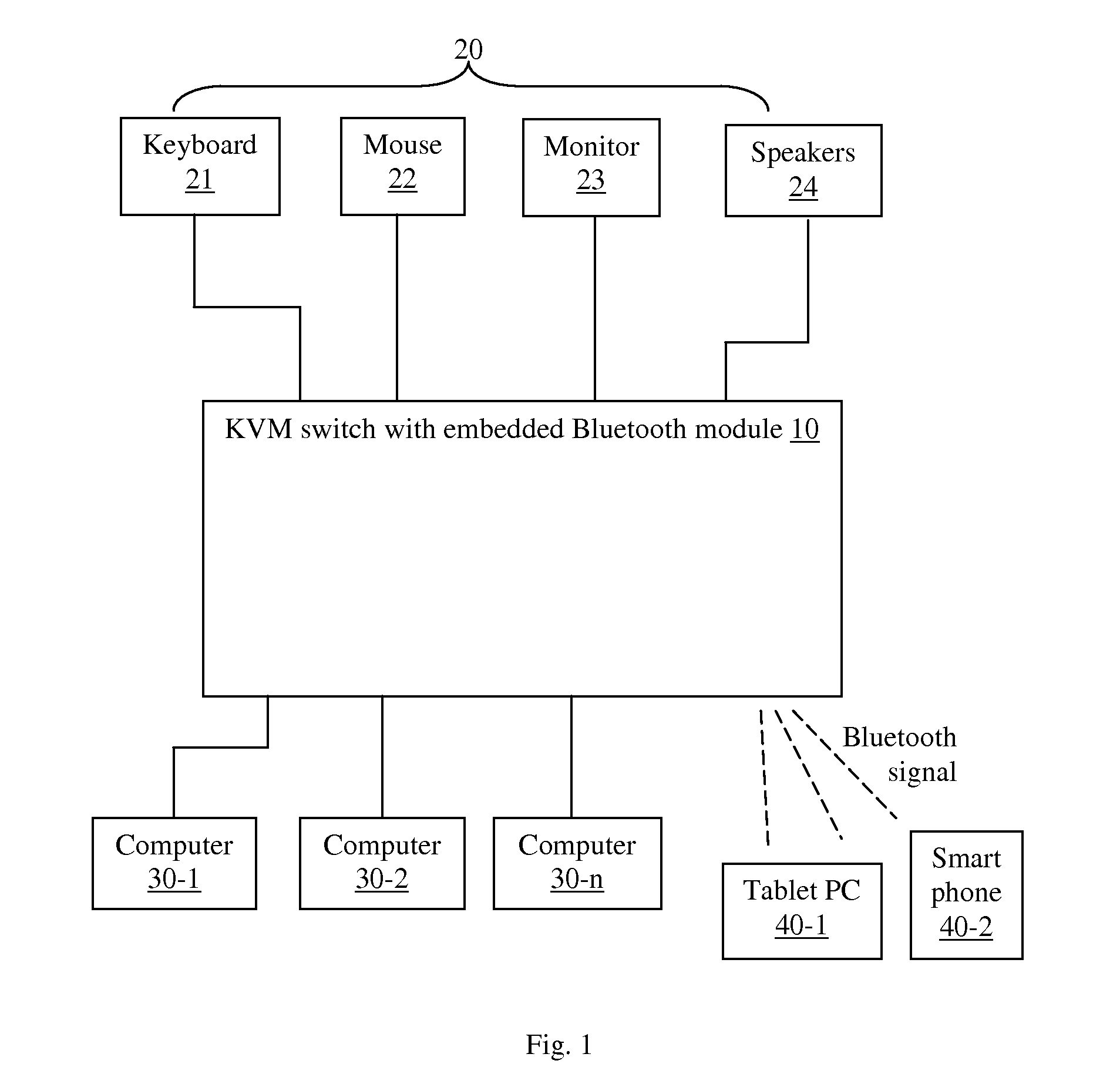
[0024]FIG. 1 illustrates a KVM switch system according to the present invention. The system includes a KVM switch 10 which has an embedded Bluetooth module described in more detail later. A user console 20 including a keyboard 21, a mouse 22, a monitor 23, and (optionally) speakers 24 is connected to the KVM switch 10 by cables. The keyboard 21 and mouse 22 may be collectively referred to as user input devices. Other user input devices such as joystick, gamepad, etc. may also be used. The connections between the KVM switch 10 and the keyboard 21 / mouse 22 may include PS / 2 or USB connection. The connections between the KVM switch 10 and the monitor 23 may be VGA or other suitable video connections. Although only one user console 20 is shown, a KVM (sometimes referred to as a matrix KVM) can be connected to multiple user consoles.

[0025]A plurality of computers 30-1 to 30-n are connected to the KVM switch 10. The computers 30-1 to 30-n may be non-Bluetooth enabled computers. The connect...

second embodiment

[0051]FIG. 4 illustrates a computer switch system according to the present invention. The system includes a switch device 10A with an embedded Bluetooth module. The switch device 10A is preferably in the form of a dongle connected between a keyboard 21 and a computer 30A. The connections between the switch device 10A and the keyboard 21 may be PS / 2 or USB connections. Alternatively, the switch device 10A may be connected to both the keyboard 21 and a mouse and the computer 30A.

[0052]The computer 30A is preferably a desktop or laptop computer with its own monitor. Thus, the user uses the keyboard 21 to interact with the computer 30A in a conventional way. However, by using the switch device 10A, the user can now use the same non-Bluetooth keyboard 21 to input keyboard data for Bluetooth master machines such as tablet computer 40-1, smart phone 40-2, etc.

[0053]FIG. 5 is a block diagram illustrating a structure of the switch device 10A of the second embodiment. The switch device 10A ha...


PUM


Abstract

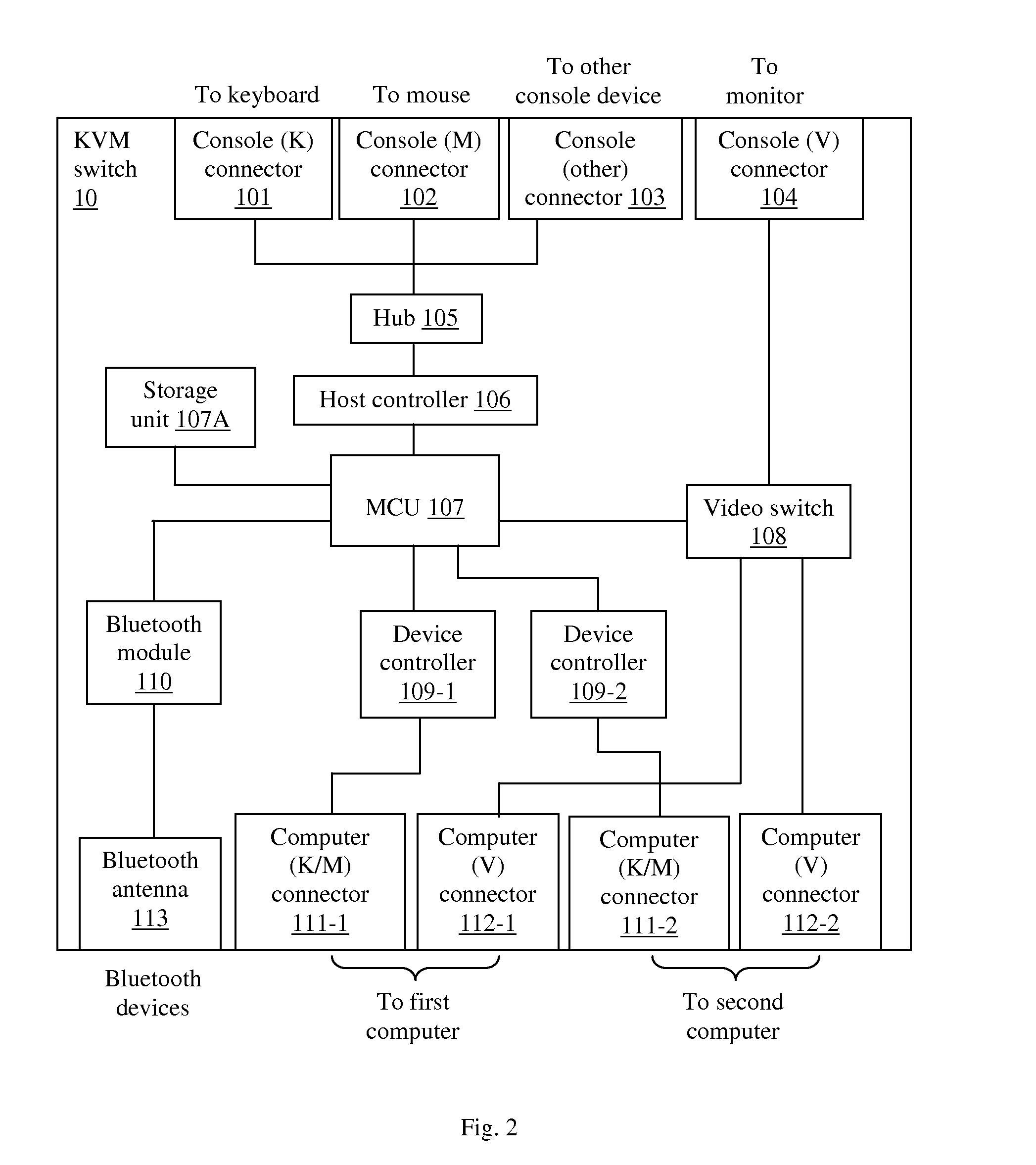
A switch device that allows a user to use the same non-Bluetooth user console (e.g., keyboard, mouse) to control both non-Bluetooth computers and Bluetooth master machines such as tablet computers, smart phones, etc. The switch device includes a console port for connecting to the console and one or more computer ports for connecting to one or more computers, as well as a Bluetooth module for communicating with Bluetooth master machines. A controller processes input device data received via the console port, and either sends the data to a selected Bluetooth master machine or a selected computer, or perform other functions such as switching, Bluetooth device pairing and disconnecting based on the input device data. The controller stores link information of the Bluetooth master machines already paired with the computer switch for quickly switching to a Bluetooth master machine. The switch device can be with or without video switching.

Description

[0001]This application claims priority under 35 USC §119(e) from U.S. Provisional Patent Application No. 61 / 482,854, filed May 5, 2011, which is herein incorporated by reference in its entirety.BACKGROUND OF THE INVENTION[0002]1. Field of the Invention[0003]This invention relates to a switch for computer equipment, and in particular, it relates to such a switch having embedded Bluetooth module that allows a non-Bluetooth enabled user console to input data for Bluetooth master machines.[0004]2. Description of the Related Art[0005]A keyboard, video, mouse (KVM) switch is a hardware device that can be connected to multiple computers and one or more user consoles, such that each user console may be selectively switched to control any one of the computers. Each user console typically includes a display device (monitor) and user input devices such as a keyboard and a mouse, as well as other devices such as speakers. When a user console is connected to a selected computer by the KVM switch...

Claims


Application Information

Patent Timeline
IPC IPC(8): G06F13/00
CPCG06F3/023G06F3/0231G06F3/033G06F3/038G09G2370/24G06F3/14G06F2203/0384G09G2370/20G06F3/0489
Inventor TUNG, SHU-CHINGTSAI, PING-WENYU, HSIANG-JUIHSUEH, CHAO-HSUAN
Owner ATEN INT CO
Learn More